Multistage centrifugal compressor and air conditioning unit

A technology for centrifugal compressors and air-conditioning units, which is applied in compressors, machines/engines, refrigerators, etc., and can solve problems such as affecting the reliable operation of compressors and units, high unit manufacturing and maintenance costs, and difficulty in meeting customer requirements. , to achieve the effect of compact structure, small footprint and small axial force

Inactive Publication Date: 2015-03-18
GREE ELECTRIC APPLIANCES INC
View PDF5 Cites 10 Cited by
  • Summary
  • Abstract
  • Description
  • Claims
  • Application Information

AI Technical Summary

Problems solved by technology

If the external dimensions of the impeller are kept constant and the speed is increased, it is very likely that the speed of the rotating parts will approach or reach the inherent critical speed and cause resonance, which will affect the reliable operation of the compressor and the unit.
[0005] In order to solve the problem of insufficient pressure ratio of a single compressor, at present, it is also solved by connecting multi-stage compressors or units in series, but this will undoubtedly cause the overall manufacturing and maintenance costs of the unit to be too high, the overall size is too large, and the supporting machine room Disadvantage of too large floor area, it is difficult to meet the actual use requirements of customers

Method used


Image

  • Multistage centrifugal compressor and air conditioning unit
  • Multistage centrifugal compressor and air conditioning unit
  • Multistage centrifugal compressor and air conditioning unit

Examples


Embodiment Construction

[0040] In order to solve the problem of too small pressure ratio, a multi-stage centrifugal compressor and air-conditioning unit are proposed.

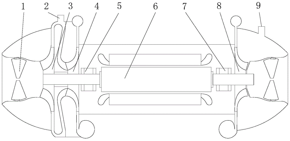
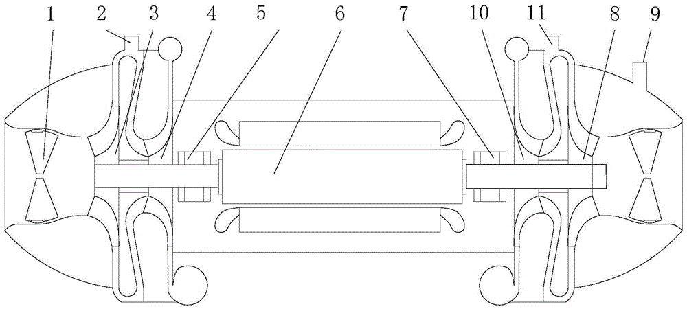
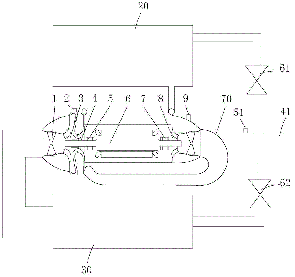
[0041] The invention provides a multi-stage centrifugal compressor, which includes a power part and an impeller part, the power part includes a motor, the motor includes a shaft, and the shaft includes a first end of the shaft and a second end of the shaft;

[0042] The impeller part includes N impellers, where N is greater than or equal to 2 and less than 10;

[0043] When N is an even number, the number of impellers on the first end of the shaft and the second end of the shaft is equal;

[0044] When N is an odd number, the number of impellers on the first end of the shaft is one more than the second end of the shaft;

[0045] The first-stage impeller is placed on the first end of the shaft, and the distance from the motor is farthest; the rest of the impellers on the first end of the shaft are arranged in ascending order;

[0046...


PUM


Abstract

A multi-stage centrifugal compressor and an air conditioning unit are disclosed. The multi-stage centrifugal compressor comprises a power part and an impeller part. The power part comprises a motor (6), the shaft of which comprises a first end and a second end. The impeller part comprises N impellers, wherein N is more than or equal to 2 and less than 10. When N is an even, the number of the impellers on the first end of the shaft is equal to that of the impellers on the second end of the shaft. When N is a singular, the number of the impellers on the first end of the shaft is one more than that of the impellers on the second end of the shaft. The first-stage impeller farthest away from the motor (6) is arranged at the first end of the shaft. The other impellers at the first end of the shaft are arranged in ascending order. The N-stage impeller nearest to the motor (6) is arranged at the second end of the shaft. The other impellers at the second end of the shaft are arranged in descending order. Air outlets of the impellers at the first end of the shaft are communicated with air inlets of the impellers at the second end of the shaft through connecting pipes so that the pressure ratio and the energy efficiency are increased.

Description

technical field [0001] The invention relates to the technical field of compressors and air conditioners, in particular to a multistage centrifugal compressor and an air conditioner unit. Background technique [0002] In the prior art, the current refrigeration centrifuges often use one-stage compression and two-stage compression. In the commonly used refrigeration range, such as chilled water inflow and outflow 12 / 7°C, cooling water inflow and outflow 30 / 35°C, because at this water temperature The pressure ratio is not high, so there are many applications of one-stage compression and two-stage compression units. When the chilled water inlet and outlet temperature remains unchanged at 12 / 7°C, while the cooling water outlet temperature is relatively high, such as 70°C outlet water, the required pressure ratio of the unit is as high as 6.5, and this working condition is most industrial manufacturing equipment, heating Required in the field of heat exchange. [0003] In order ...

Claims


Application Information

Patent Timeline
Patent Type & Authority Applications(China)
IPC IPC(8): F04D25/16
CPCF04D29/60F04D17/12F04D29/441F04D27/0238F04D25/06F04D29/4206F25B41/39F04D25/08F04D29/053F04D29/058F04D29/059F04D29/286F25B31/00F25B33/00
Inventor 钟瑞兴夏光辉刘华张治平蒋楠谢蓉闫秀兵王宏兴
Owner GREE ELECTRIC APPLIANCES INC
Why Eureka
Try Eureka