Optical scanning unit, and apparatus including the optical scanning unit

An optical scanning device and image technology, applied in the field of vehicles, can solve the problems of stable scanning of the scanned surface and the inability of abnormal images, and achieve the effect of preventing abnormal images and stabilizing scanning.

Inactive Publication Date: 2015-03-18
RICOH KK
View PDF5 Cites 11 Cited by
  • Summary
  • Abstract
  • Description
  • Claims
  • Application Information

AI Technical Summary

Problems solved by technology

[0004] However, in the optical scanning unit disclosed in Patent Document 1, the light emitted by the light source is affected by the reflected light on the surface of the light-transmitting window member, and abnormal images may appear on the scanned surface or stable scanning of the scanned surface may not be possible. The problem

Method used


Image

  • Optical scanning unit, and apparatus including the optical scanning unit
  • Optical scanning unit, and apparatus including the optical scanning unit
  • Optical scanning unit, and apparatus including the optical scanning unit

Examples


Deformed example 1

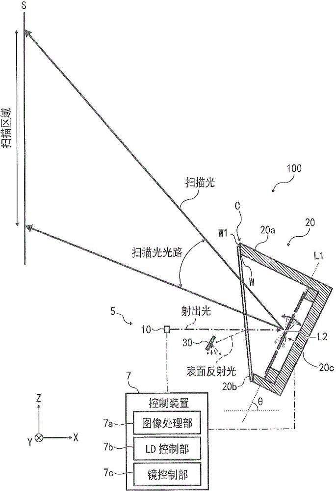
[0066] Figure 5 It is a schematic diagram of the projection apparatus 200 shown in Modification 1. FIG. Such as Figure 5 As shown, the positional relationship between the glass cover 20b and the mirror 20c can also be set such that, on an imaginary plane parallel to the Y axis (viewed from the -Y side), the optical path of the emitted light and the optical path of the scanning light are respectively located on the surface On both sides of the optical path of reflected light, in other words, viewed from the -Y side, the optical path of surface reflected light is sandwiched between the optical path of emitted light and the optical path of scanning light.

[0067] In Modification 1, the light shielding member 30 also blocks the surface reflected light, prevents the surface reflected light from entering the scanning area, and prevents the surface reflected light from entering the LD 10 . Compared with the above-mentioned embodiment, Modification 1 can reduce the angle between ...

Deformed example 6

[0077] Figure 10 is a schematic diagram of a projection device 700 according to Modification 6. FIG. Such as Figure 10 As shown, the glass cover 24b is parallel to the reference plane (the plane including the first axis L1 and the second axis L2).

[0078] In Modification 6, the unit 24a of the light deflector 24 is a parallel unit, and is composed of a substantially U-shaped XZ section. and Figure 4 The comparative example shown is the same, and the light reflected from the surface is directed to the optical path of the scanning light.

[0079] The light shielding member 30 in Modification 6 is provided on the optical path (travel path) of the surface reflected light and away from the optical path of the scanning light so that the surface reflected light can be blocked. It is preferable to adjust the posture of the light shielding member 30 so that the light reflected (scattered) by the light shielding member 30 does not enter the LD 10 and the light deflector 24 .

[0...

Deformed example 7

[0082] Figure 11 is a schematic diagram of an optical deflector 26 according to Modification 7. FIG. Such as Figure 11 As shown, an assembly 26a (first holding portion) for holding the mirror 20c and a holding member 26c (second holding portion) for holding the glass cover 26b in the light deflector 26 are combined.

[0083] By adopting the above structure, not only can the module 26a be used as a parallel module, but also the glass cover 26b can be installed obliquely with respect to the reference plane.

[0084] Modification 7 facilitates assembly processing and has the same effect as the above-described embodiment.

[0085] The image projection devices of the above-mentioned embodiments and various modifications using light deflectors are all projection devices, but the present invention is not limited thereto. As an image forming device, for example Figure 12 Light deflectors are also used in the Head Up Display 1000 shown. Generally, the head-up display 1000 is ins...


PUM


Abstract

An optical scanning unit (5) includes a light source (10), an optical deflector (20) that includes a light transmission window (20b, 22b, 24b, 26b) disposed on a light path from the light source (10) and a rotatable mirror (20c) that includes a reflecting surface to reflect light that goes through the light transmission window (20b, 22b, 24b, 26b) into the light transmission window (20b, 22b, 24b, 26b) and to deflect the light from the light source (10) toward a surface, and a light shield (30) disposed on a light path of reflected light of the light from the light source (10) reflected by a surface of the light transmission window (20b, 22b, 24b, 26b).

Description

technical field [0001] The present invention relates to an optical scanning device, an image forming device, and a vehicle, and more particularly, to an optical scanning device for optically scanning a surface to be scanned, an image forming device including the optical scanning device, and a vehicle including the image forming device. Background technique [0002] Currently, for example, there is an optical scanning unit disclosed in Patent Document 1 (JP-A-2006-221171 ), which uses light emitted from a light source to optically scan a surface to be scanned. [0003] The light scanning assembly has a light-transmitting window part and a rotatable reflector, the light-transmittance window part is arranged on the optical path of the light emitted by the light source, and the rotatable reflector is used to reflect the incident light through the light-transmittance window part, so that The light is directed toward the light transmissive window member. It also has a light defle...

Claims


Application Information

Patent Timeline
Patent Type & Authority Applications(China)
IPC IPC(8): G02B26/12G03G15/00
CPCG02B26/105G02B2027/0145G02B26/0833G02B26/101G02B26/10G02B26/0841G02B27/0018B81B2201/047G02B27/0101B81B7/0067
Inventor 市井大辅
Owner RICOH KK
Why Eureka
Try Eureka