Thin combined inductor structure and assembly method thereof

An assembly method and inductor technology, applied in the directions of transformer/inductor coil/winding/connection, inductor/transformer/magnet manufacturing, inductor with magnetic core, etc., can solve problems such as divergence of magnetic force line loop and change of inductance value, Achieve the best assembly yield and improve production efficiency

Inactive Publication Date: 2015-03-18
重庆美桀电子科技有限公司
View PDF5 Cites 2 Cited by
  • Summary
  • Abstract
  • Description
  • Claims
  • Application Information

AI Technical Summary

Problems solved by technology

[0005] Furthermore, it is known that if the inductance element is in a skewed state after the shell 13 and the core 10 are assembled, a gap will be generated between the shell 13 and the outer edge, which will cause the divergence of the magnetic flux loop and the change of the inductance value.

Method used


Image

  • Thin combined inductor structure and assembly method thereof
  • Thin combined inductor structure and assembly method thereof
  • Thin combined inductor structure and assembly method thereof

Examples


Embodiment Construction

[0041] The present invention provides a thin combined inductor structure and its assembly method. In order to make the purpose, technical solution and advantages of the present invention clearer and clearer, the present invention will be further described in detail below with reference to the accompanying drawings and examples. It should be understood that the specific embodiments described here are only used to explain the present invention, not to limit the present invention.

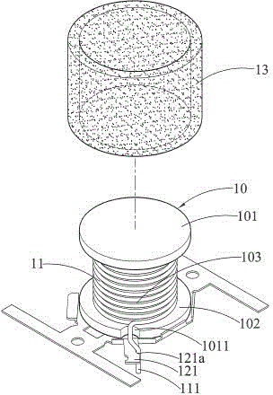
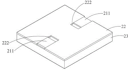
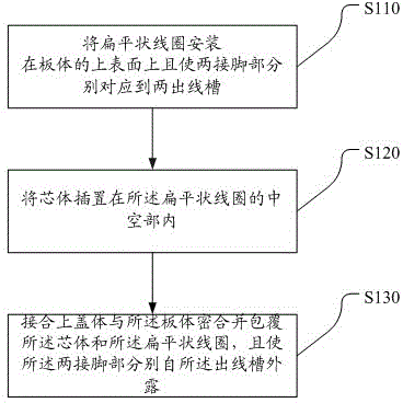
[0042] A preferred embodiment of a thin combined inductor structure provided by the present invention, such as figure 2 and Figure 3b As shown, the inductor structure includes: a core body 20, a flat coil 21, a board body 22, and an upper cover body 23, wherein the flat coil 21 can be installed on the board body 22, and the core body 20 is sleeved on the In the hollow part 212 of the flat coil 21, or after the core body 20 is placed on the board body 22, the flat coil 21 is installed on the board b...


PUM


Abstract

The invention discloses a thin combined inductor structure and an assembly method thereof. The thin combined inductor structure comprises a core, a flat coil, a board and an upper cover; the flat coil which is hollow comprises two pin parts extending out; the upper surface of the board is used for holding the core and the flat coil; the upper cover connected with the board is used for covering the cover and the flat coil. In this way, after the core is mounted on the board, by the use of the flat coil allowing the core to be nested in, the core, the board and the upper cover, wherein the core, the board and the upper cover are separated, the problems that non-uniform winding is caused in the prior winding process, parts are difficult to separately manufactured, making use of magnetic materials different in magnetic characteristic is difficult and the shifting of wire ends cause failure of the wire ends to be passed out of hanging slots are avoided.

Description

technical field [0001] The present invention relates to an inductor structure and an assembly method thereof, in particular to a thin combined inductor structure with a flat coil in which a core can be sheathed, and an assembly method of the inductor structure. Background technique [0002] In the current field of electronic components, inductance elements are often used as passive elements in electronic circuits, and the function of the inductance element is usually as a filter for suppressing high-frequency signals in high-frequency circuits. figure 1 It is a structural diagram of a known inductance element, wherein the inductance element has a core 10 , a coil 11 , a base 12 , and a casing 13 . The core 10 is made of an I-shaped magnetic material, and has an upper core plate 101 , a lower core plate 102 , and a column 103 integrally formed. The core lower plate 102 is connected to the lower surface of the cylinder 103, and optionally has an outlet groove 1011 for the two...

Claims


Application Information

Patent Timeline
Patent Type & Authority Applications(China)
IPC IPC(8): H01F17/04H01F27/28H01F27/30H01F41/00
Inventor 罗鹏程
Owner 重庆美桀电子科技有限公司
Why Eureka
Try Eureka