
Electronic device

An electronic device and electrical connection technology, applied in the direction of electrical digital data processing, instruments, digital data processing components, etc., can solve the problems of poor assembly or disassembly efficiency, touch panel damage, etc., and achieve the best maintenance efficiency and best The effect of assembly yield

Inactive Publication Date: 2013-08-21
SHUN ELECTRONICS
View PDF5 Cites 7 Cited by
  • Summary
  • Abstract
  • Description
  • Claims
  • Application Information

AI Technical Summary

Problems solved by technology

Therefore, when the assembler needs to assemble or disassemble the touch panel, it often causes the touch panel to be luminously shifted during assembly or destructively damaged during the disassembly process, and the efficiency of assembly or disassembly is not good.

Method used


Image

  • Electronic device
  • Electronic device

Examples


Embodiment Construction

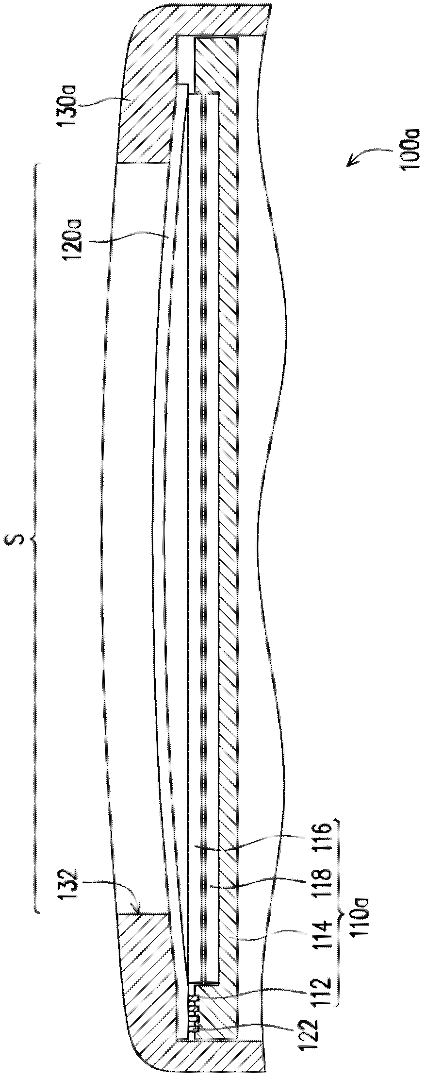
[0037] figure 1 It is a schematic cross-sectional view of an electronic device according to an embodiment of the present invention. Please refer to figure 1 , in this embodiment, the electronic device 100a includes a display module 110a and a touch panel 120a. In detail, the display module 110a has at least one first connector 112 ( figure 1 Only one is schematically shown in ), where the display module 110 a is composed of a frame body 114 , a display panel 116 and a backlight module 118 . The first connector 112 is disposed on the frame body 114 . The display panel 116 is disposed in the frame body 114 and electrically connected to the first connector 112 . The backlight module 118 is disposed in the frame body 112 and located between the frame body 114 and the display panel 116 . Here, the display module 110a is, for example, a liquid crystal display module (LCM), a plasma display module or an organic electroluminescence display, but not limited thereto. The first conn...


PUM


Abstract

The invention discloses an electronic device which comprises a display module and a touch panel. The display module is provided with at least one first connector. The touch panel is configured on the display module and is provided with a second connector. The second connector is connected onto the corresponding first connector in inserting mode so as to lead the touch panel to be assembled and electrically connected onto the display module.

Description

technical field [0001] The present invention relates to an electronic device, and in particular to an electronic device with a touch panel. Background technique [0002] In today's information society, human beings are increasingly dependent on consumer electronic devices. Mobile phones, personal digital assistants (PDAs), and tablet PCs (Tablet PCs) can be seen everywhere in our lives. Therefore, consumer electronic devices are inseparable from the daily life of modern people. In order to achieve more convenience, smaller size and more user-friendly, many products have changed from traditional input devices such as keyboards or mice to use touch screens as input devices. [0003] Generally speaking, a touch screen is composed of a touch panel and a display panel. Because the design of the touch panel must match the appearance, the touch panel and the display panel are assembled separately on the product. However, most of the existing touch panels are fixed on the product...

Claims


Application Information

Patent Timeline
Patent Type & Authority Applications(China)
IPC IPC(8): G06F1/16
Inventor 王仁宏张君勇洪铭杰李联鑫李昭松
Owner SHUN ELECTRONICS
Learn More