Optical imaging lens

An optical imaging lens and lens technology, applied in the field of optical imaging, can solve problems affecting the quality of optical imaging, inaccurate assembly, eccentricity of optical imaging lens, etc., and achieve the effect of good optical imaging quality and good assembly yield

Pending Publication Date: 2022-02-22
GENIUS ELECTRONICS OPTICAL XIAMEN
View PDF0 Cites 0 Cited by
  • Summary
  • Abstract
  • Description
  • Claims
  • Application Information

AI Technical Summary

Problems solved by technology

In addition, in the past, even if the distance between the optical element of the optical imaging lens and the mounting part of the lens barrel is very close, a distance of more than 30 microns will be maintained, so that the burr of the lens will not touch the mounting part, causing the problem of inaccurate assembly , when the maximum outer diameter of the lens is much larger than the maximum outer diameter of the previous lens, the optical elements such as the lens, the shading element, and the lens barrel mounting part may be unbalanced in torque during assembly, resulting in deformation of the shading element or causing the entire optical imaging lens Eccentricity will affect the quality of optical imaging and other issues

Method used


Image

  • Optical imaging lens
  • Optical imaging lens
  • Optical imaging lens

Examples


Embodiment Construction

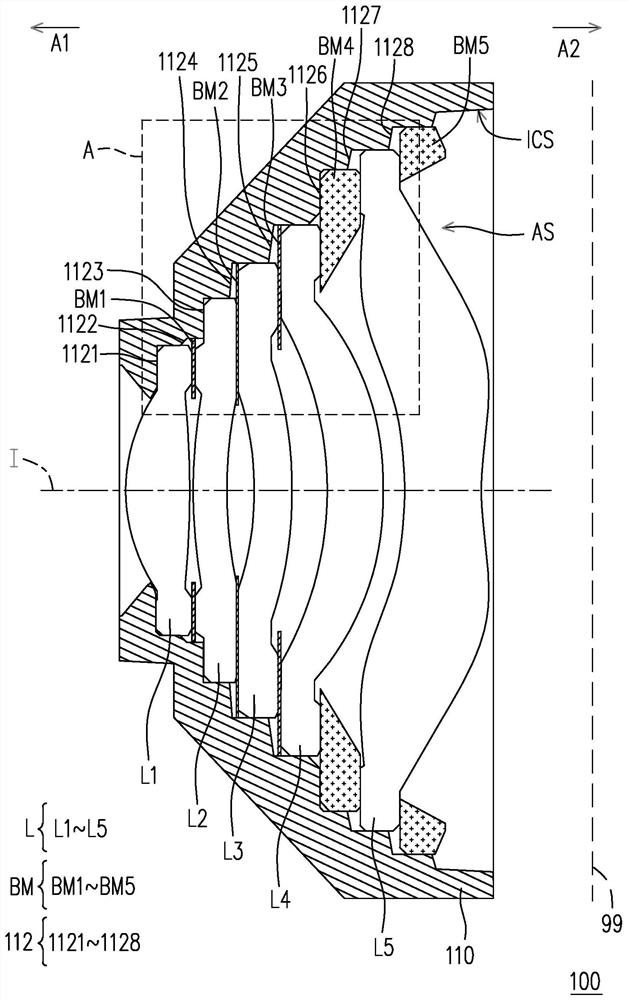
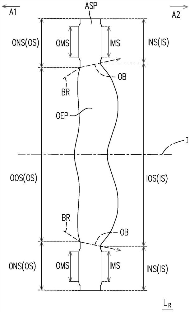
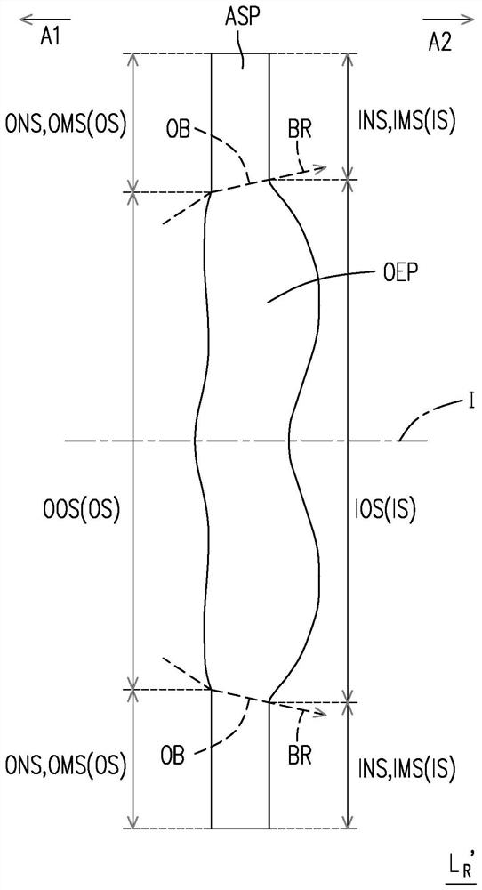
[0035] Before starting to describe the present invention in detail, first clearly indicate the symbols in the drawings: 100, 100a: optical imaging lens; 110, 110a: lens barrel; 112, 1121-1129: installation part; 99: imaging surface; A, B , C, E, F, G: area; A1: object side; A2: image side; AS: installation space; ASP: assembly department; BM, BM', BM1~BM5, BM1'~BM9': shading element; BR : imaging light; CF1, CF2, CF1', CF2': chamfering; d, D, d', D': clearance; D1, D2, RA1~RA4: vertical distance; F1~F6: bearing force; H: Direction; I: optical axis; ICS: inner peripheral surface; IOS: image side optical surface; INS: image side optical ineffective surface; IMS, IMS1~IMS6: image side mechanical surface; L, L1~L6: lens; L R , L R ': reference lens; OEP: optically effective part; OS: object side; OOS, OOS1: object-side optically effective surface; ONS: object-side optically inactive surface; OMS, OMS1~OMS6: object-side mechanical surface; P1, P2: fulcrum ;S1, S2, S1', S2': recei...


PUM


Abstract

The invention discloses an optical imaging lens which comprises a lens barrel, a plurality of lenses and a shading element. The lens barrel has a mounting part. Each lens is provided with an object side mechanical surface and an image side mechanical surface which face the object side and the image side respectively. The shading element is made of metal or plastic. The optical imaging lens satisfies the following conditional expression according to the material of the shading element: -200 microns < RA1-RA2 < = 450 microns or -200 microns < = RA1-RA2 < =-300 microns. In addition, the mounting part can bear the shading element. The mounting part is provided with a bearing surface facing the image side. The receiving surface and the optical element closest to the receiving surface have a minimum distance in the direction parallel to the optical axis. The minimum distance is less than or equal to 5.000 microns. The optical imaging lens has good assembly yield and optical imaging quality.

Description

technical field [0001] The invention relates to the field of optical imaging, in particular to an optical imaging lens. Background technique [0002] In recent years, the optical imaging lens has been continuously evolving. In addition to requiring the lens to be light and thin, the imaging quality of the lens is also important. In addition to the parameters such as the surface shape of the lens or the air gap between the lenses that will affect the optical imaging quality, the lens and the shading element are assembled. The stability of the camera is also a major factor affecting the quality of optical imaging. [0003] In order to develop better optical imaging quality and reduce the area ratio of the lens to the screen of the portable electronic device, the maximum radius of the lens closest to the object side is designed to be smaller and smaller, and the maximum radius of the lens closer to the image side is relatively larger . In addition, in the past, even if the di...

Claims


Application Information

Patent Timeline
Patent Type & Authority Applications(China)
IPC IPC(8): G02B7/02G02B7/00G03B17/02G03B17/12G03B30/00
CPCG02B7/021G02B7/00G03B17/02G03B17/12G02B13/0045G02B9/60G02B5/003
Inventor 陈文森魏初滋
Owner GENIUS ELECTRONICS OPTICAL XIAMEN
Why Eureka
Try Eureka