Method for compositing cooling tube and fin piece and composition thereof

A combination method and heat pipe technology, applied in the cooling of the instrument, the parts of the instrument, cooling/ventilation/heating transformation, etc., can solve the problems of falling tin material, prolonging the manufacturing time, and affecting the yield in production.

Inactive Publication Date: 2008-12-24
TAI SOL ELECTRONICS
View PDF1 Cites 2 Cited by
  • Summary
  • Abstract
  • Description
  • Claims
  • Application Information

AI Technical Summary

Problems solved by technology

[0005] In the above method, the fins are stacked after the tin material is placed. In fact, the fins are in a hot melt state when the tin material is placed (Fig. 3 (b)). In order to prevent the tin material from running around when stacking, Usually, the stacking is started after the tin material is solidified. This situation will prolong the manufacturing time. In addition, the tin material is placed first be

Method used


Image

  • Method for compositing cooling tube and fin piece and composition thereof
  • Method for compositing cooling tube and fin piece and composition thereof
  • Method for compositing cooling tube and fin piece and composition thereof

Examples


Embodiment Construction

[0020] In order to describe in detail the technical features of the present invention, hereby give the following two preferred embodiments and describe them as follows in conjunction with the accompanying drawings, wherein:

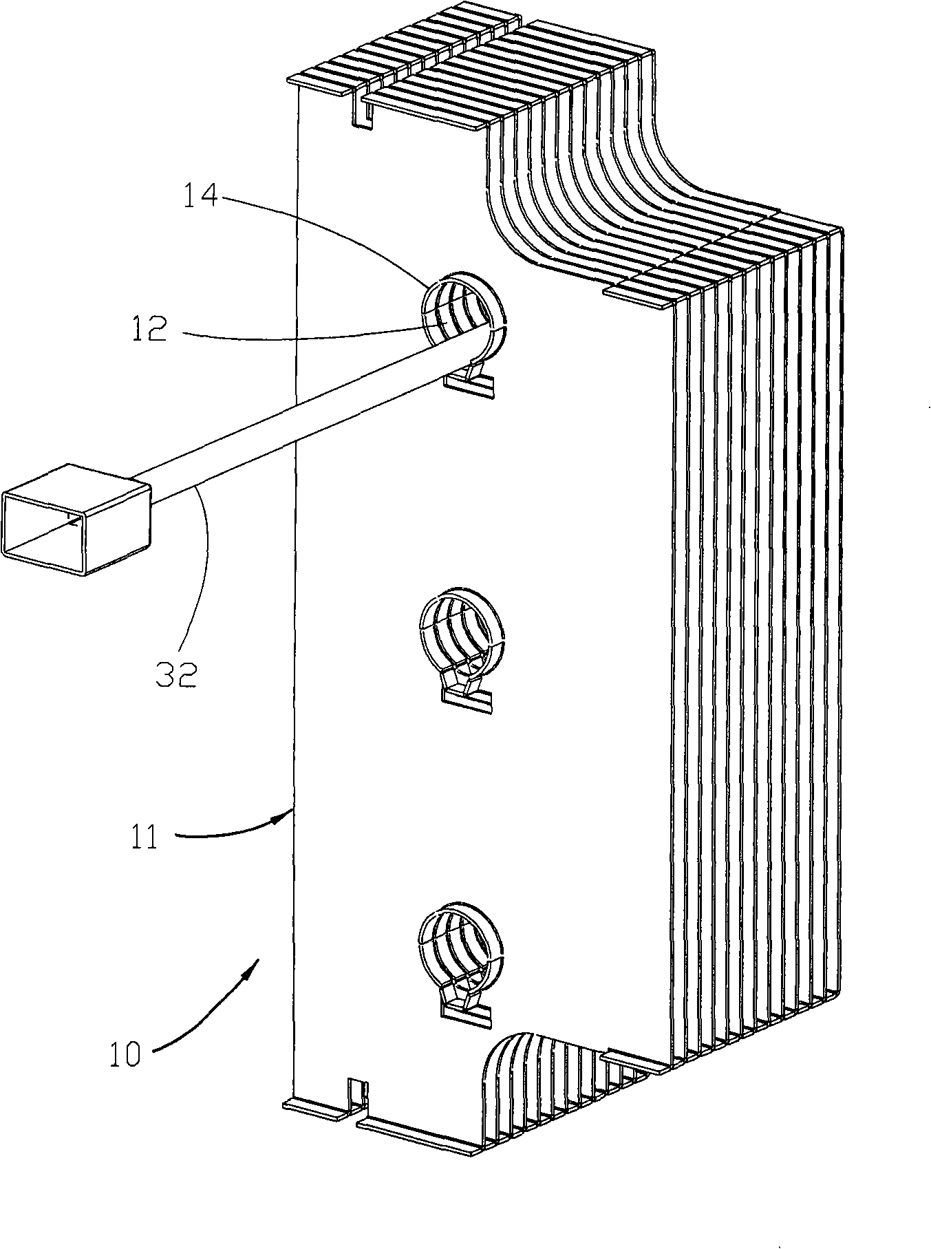
[0021] For the convenience of illustration, in the drawings of the present invention, only one heat pipe 21 is used to represent the state of passing through the through hole 12 .

[0022] Such as Figure 1 to Figure 7 As shown, the method for combining heat pipes and fins provided by the first preferred embodiment of the present invention mainly has the following steps:

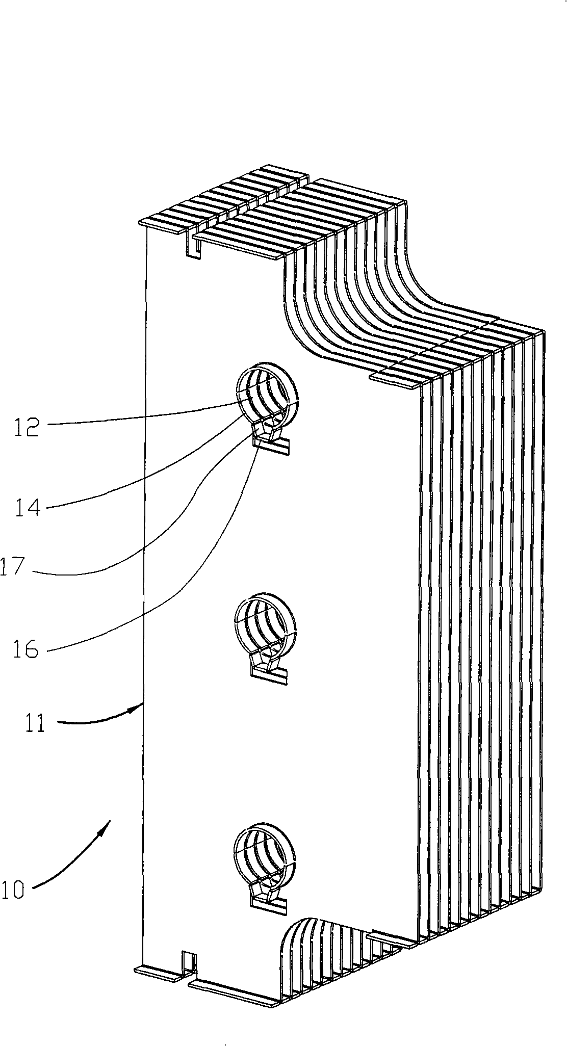
[0023] a) Prepare several fins 11 and several heat dissipation pipes 21: the fins 11 are stacked one above the other, each of the fins 11 has several perforations 12, and the perforations 12 on each of the fins 11 correspond to each other And allow these radiating pipes 21 to pass through, each side of each fin 11 extends outwards an extension wall 14 along the periphery of each hole 1...


PUM


Abstract

The invention relates to a combining method of cooling tubes and fins and an assemblage thereof, wherein, the method mainly combines a plurality of fins and at least one cooling tube; the fins are mutually superimposed and provided with at least one through hole corresponding to each other; one side of each fin extends outside to form an extension wall along the circumference of the through hole; one side of each extension wall forms a first opening; furthermore, each fin forms a holding part provided with a second opening corresponding to the first opening; solder is injected into the holding part; the cooling tube is penetrated into the through hole; then, the fins are turned over so as to cause the first opening to turn upward; heating is carried out to melt the solder which flows to the first opening from the second opening and flows to a clearance between the cooling tube and the extension wall; combination is finished after cooling and the assemblage is formed.

Description

technical field [0001] The present invention relates to a heat dissipation device, in particular to a combination method of a heat dissipation pipe and a fin and its composition. Background technique [0002] In the heat dissipation device, taking the heat sink as an example, it is generally composed of a base and several upright fins arranged on the base, and the area in contact with the air is increased by these fins, thereby achieving better cooling effect. [0003] In addition, there is also a heat dissipation device that uses a combination of heat dissipation pipes and several fins. The main reason is that the heat dissipation pipes pass through the fins, and the heat from the heat source is quickly transferred to the heat dissipation device through the high temperature uniformity of the heat dissipation pipes. and other fins, and using the fins to increase the area in contact with the air can achieve an excellent heat dissipation effect. [0004] However, the combina...

Claims


Application Information

Patent Timeline
IPC IPC(8): G12B15/06H05K7/20
Inventor 刘克平
Owner TAI SOL ELECTRONICS
Why Eureka
Try Eureka