Osteosynthesis apparatus for proximal femur fracture and master screw-type screw apparatus for osteosynthesis apparatus for proximal femur fracture

a femur fracture and osteosynthesis technology, applied in the field of proximal femur fracture osteosynthesis apparatus and master screw-type screw apparatus for proximal femur fracture, can solve the problems of cumbersome surgery, hindering surgery, and creating threads through threading, and achieves stable fixation of the proximal portion of the femur, not to loose permanently, and easy and highly stable assembly.

Inactive Publication Date: 2016-11-01
FOUR STUDIES
View PDF17 Cites 0 Cited by
  • Summary
  • Abstract
  • Description
  • Claims
  • Application Information

AI Technical Summary

Benefits of technology

[0008]An object of the present invention, which has been achieved in consideration of the above-described circumstances, is to enable swift and highly stable insertion of a lag screw into a cancellous bone and assembly of the lag screw to a nail by easily screwing a lag screw set. The lag screw set may include the lag screw, a key ring, and a fastening nut anteriorly in an axial direction while the lag screw set is guided by a key groove with respect to the nail. Further object of the present invention is to achieve a strong bone holding power, anti-rotation of the lag screw due to a forced fixing to the fastening nut, and a mechanism for retaining the lag screw set by radially inserting grip bars into the cancellous bone in an outer circumferential direction of the lag screw at the same time.

Problems solved by technology

Also, the above-described conventional guide apparatus for bone surgery has problems, such as: creating a thread by means of threading is sometimes difficult due to a density of a bone interior portion; a front end portion of the lag screw having a thread is not stably maintained in a bone head part, or the lag screw cannot be pulled off when such need arises once the lag screw is fixed by threading; and inserting various surgical tools into the guide apparatus in an alternating manner is cumbersome and hinders surgery.

Method used


Image

  • Osteosynthesis apparatus for proximal femur fracture and master screw-type screw apparatus for osteosynthesis apparatus for proximal femur fracture
  • Osteosynthesis apparatus for proximal femur fracture and master screw-type screw apparatus for osteosynthesis apparatus for proximal femur fracture
  • Osteosynthesis apparatus for proximal femur fracture and master screw-type screw apparatus for osteosynthesis apparatus for proximal femur fracture

Examples


Embodiment Construction

First Invention

Osteosynthesis Apparatus for Proximal Femur Fracture

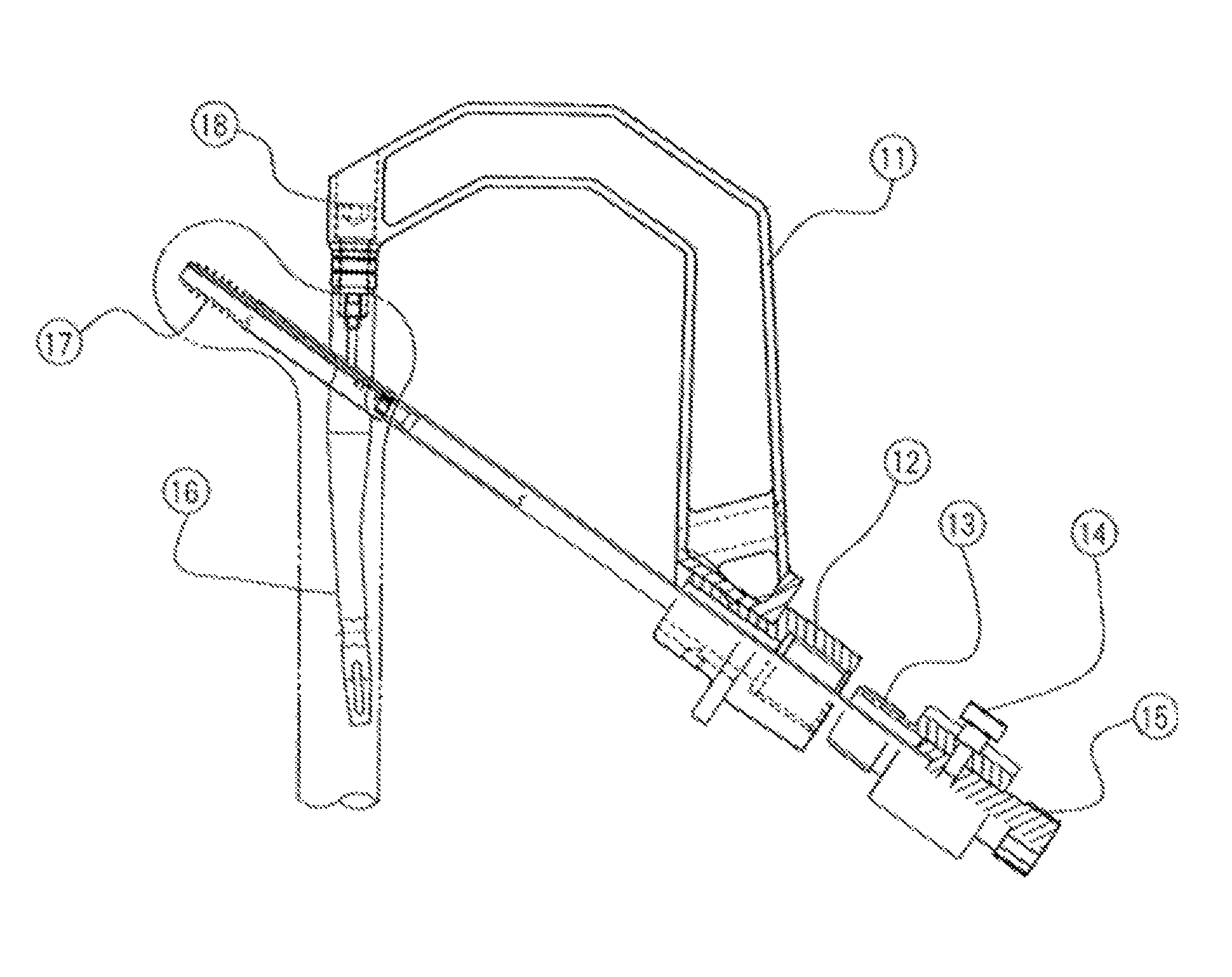
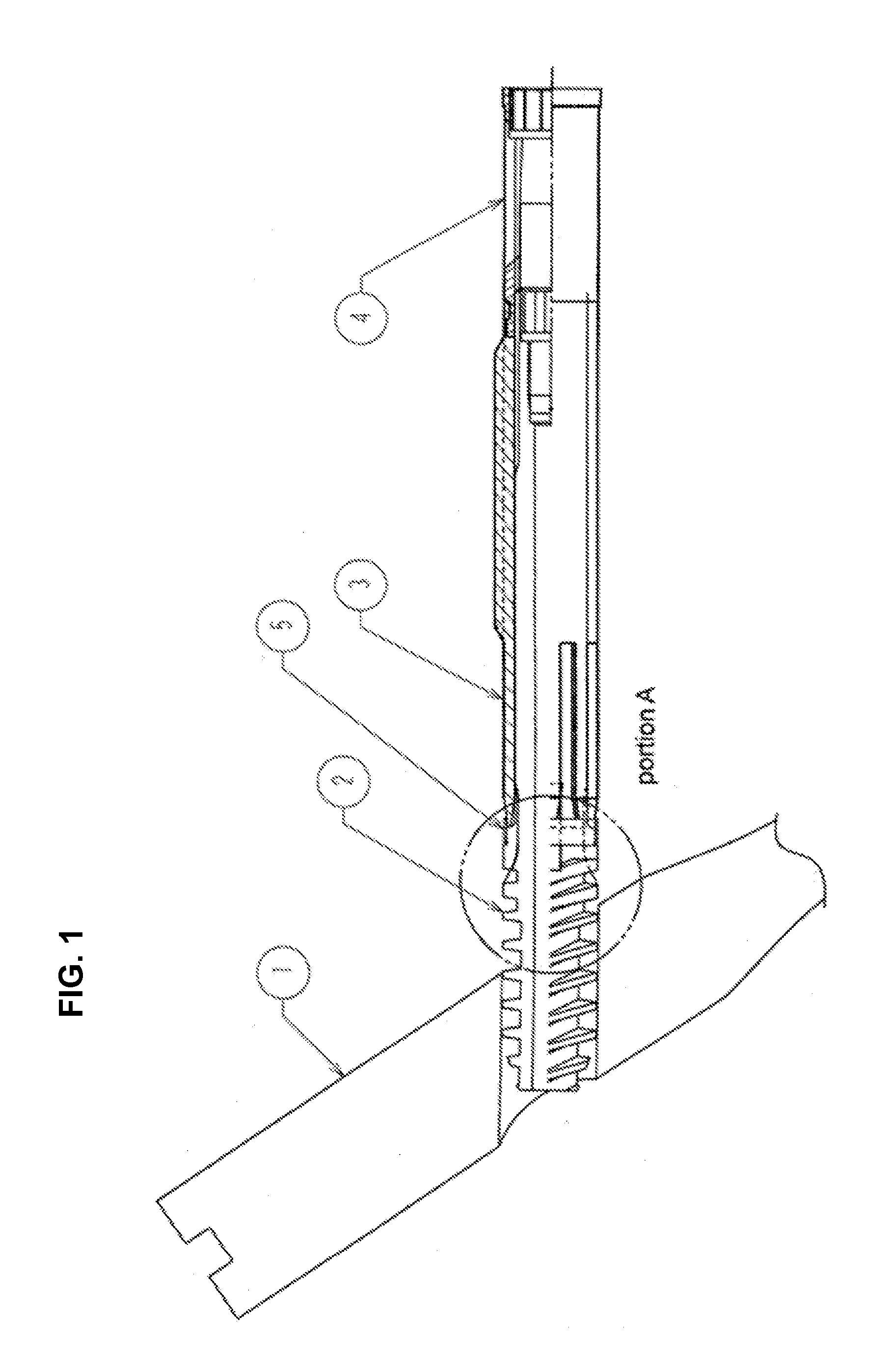
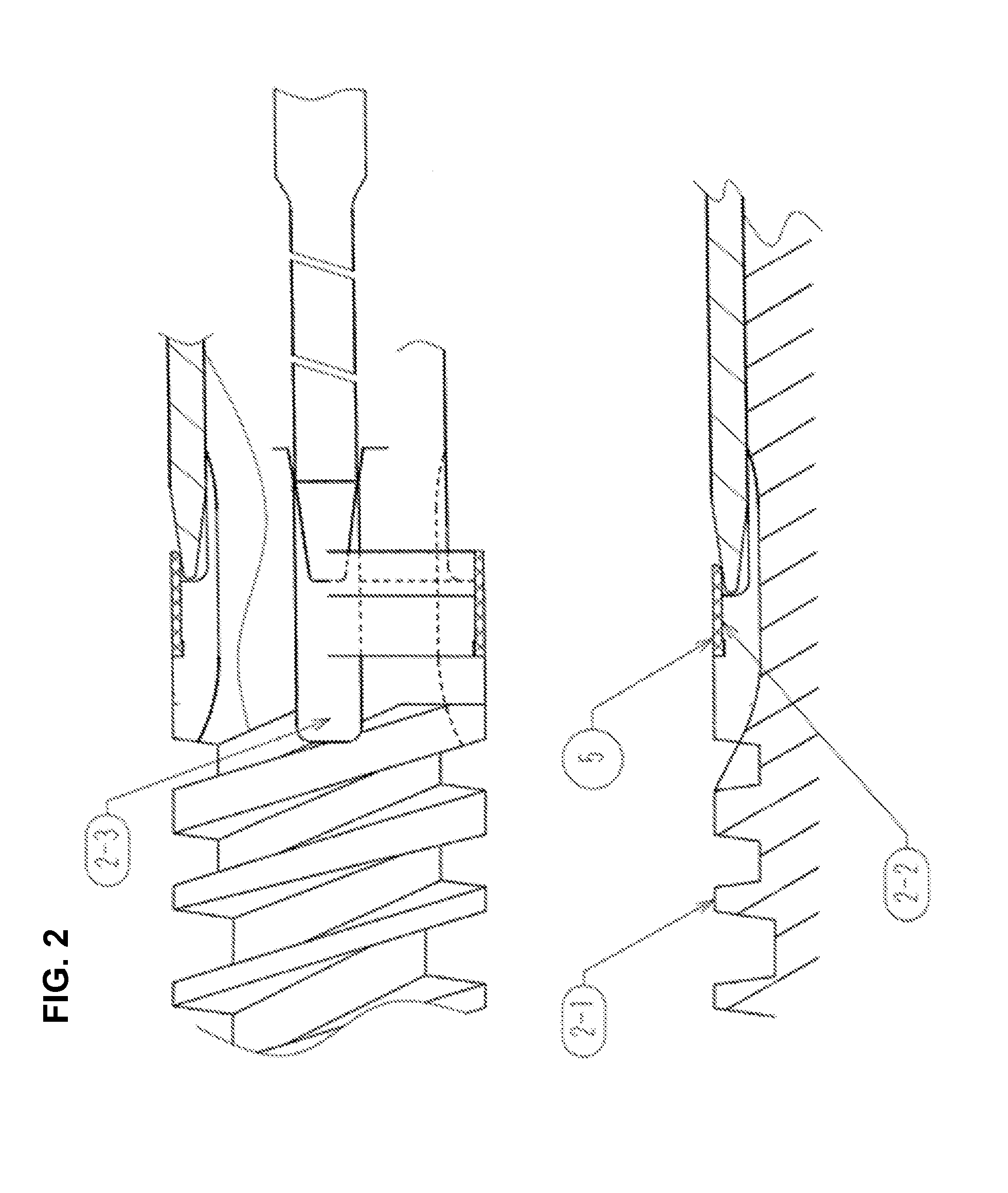
[0047]The first embodiment of the present invention will now be described with reference to FIGS. 1, 2, 3, 4, 5, 6, 7, 8, 9, 10, 11, 12, 13, 14, 15, 16, and 17. FIG. 1 is a general cross-sectional view illustrating a state of insertion, in which a lag screw set is inserted into a nail 1. In this embodiment, the lag screw set may include a lag screw 2, a key ring 3, a fastening nut 4, and a guide ring 5. FIG. 2 represents a partial detailed view of portion A shown in FIG. 1. FIG. 3 is a general cross-sectional view illustrating a state in which the lag screw set is engaged with the nail 1 with key and is screwed into a predetermined position in a bone head part. FIG. 4 is a general cross-sectional view illustrating a final state at the advance end, in which the lag screw 2 and the key ring 3 are slidingly engaged with each other and grip bars 3-1 of the key ring 3 are opened and are biting into a cancellous bone due t...


PUM


Abstract

Embodiments of the present invention provide an osteosynthesis apparatus for proximal femur fractures. The osteosynthesis apparatus for proximal femur fractures has a structure in which a lag screw set and a nail are assembled via screwing process. The lag screw is assembled with a key ring and a fastening nut in advance. When inserting this lag screw set into a bone, grip bars are inserted radially at a predetermined angle and direction, resulting in a strong bone holding power. Further, in a final step, a strong fixed coupling is achieved by forcibly screwing and engaging the lag screw and the fastening nut by an interference of the threads of the lag screw and the fastening nut. Thus, the osteosynthesis apparatus for proximal femur fractures has a strong bone holding power and is stable without loosening.

Description

[0001]This application is the U.S. National Phase of and claims priority to International Patent Application No. PCT / JP2014 / 069665, International Filing Date Jul. 25, 2014, entitled Osteosynthesis Device For Proximal Femur Fracture And Master Screw Type Screw Device For Osteosynthesis Device For Proximal Femur Fracture, which claims benefit of Japanese Patent Application No. 2013-243312 filed Nov. 7, 2013 and Japanese Patent Application No. 2014-077331 filed Mar. 17, 2014, which are hereby expressly incorporated by reference in their entirety for all purposes.TECHNICAL FIELD[0002]This invention relates to a structure of a lag screw set for implant mainly used in osteosynthesis operation of proximal femur fracture and a fixation mechanism of a nail and a lag screw. Also, this invention relates to a driving apparatus attached to a guide apparatus body (frame) for an osteosynthesis apparatus for proximal femur fracture, and particularly relates to a driving apparatus for an osteosynthe...

Claims


Application Information

Patent Timeline
Patent Type & Authority Patents(United States)
IPC IPC(8): A61B17/74A61B17/17
CPCA61B17/744A61B17/1721A61B17/74
Inventor KATO, SHIGETOSHI
Owner FOUR STUDIES
Why Eureka
Try Eureka