Conductive assembly and connection structure between conductive members

A technology of conductive components and connection structures, applied in the direction of connection where permanent deformation plays a role, can solve problems such as uneven electric field and uneven connection, and achieve the effect of avoiding electric field changes and improving insulation performance

Pending Publication Date: 2022-05-13
PINGGAO GRP
View PDF0 Cites 0 Cited by
  • Summary
  • Abstract
  • Description
  • Claims
  • Application Information

AI Technical Summary

Problems solved by technology

[0005] The purpose of the present invention is to provide a conductive component to solve the technical problem of uneven electric field caused by uneven connection between conductive parts in the prior art
T

Method used


Image

  • Conductive assembly and connection structure between conductive members
  • Conductive assembly and connection structure between conductive members
  • Conductive assembly and connection structure between conductive members

Examples


Embodiment 1

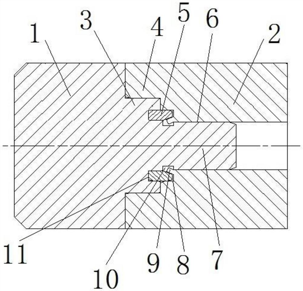
[0058] Such as figure 1 As shown, the connection structure between the conductive parts is formed by assembling the conductive components, and the conductive components include the second conductive part 2 and the first conductive part 1 . In this embodiment, the first conductive member 1 is the joint of the conductive rod, and the second conductive member 2 is the body of the conductive rod.

[0059] The second conductive part 2 and the first conductive part 1 are plugged together in an interference fit, specifically, as figure 2 As shown, the first conductive member 1 sequentially includes a large-diameter section, a middle-diameter section and a small-diameter section from left to right; image 3 As shown, the second conductive member 2 is a tubular structure as a whole, and it includes a large aperture section and a small aperture section from left to right. The inner diameter of the large aperture section is adapted to the outer diameter of the middle diameter section o...

Embodiment 2

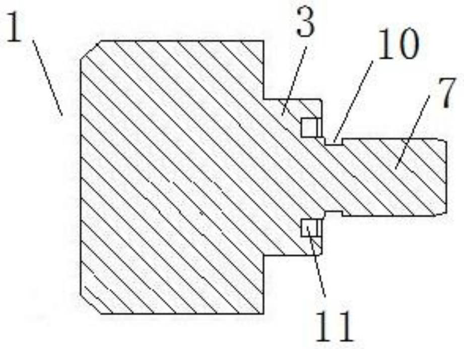
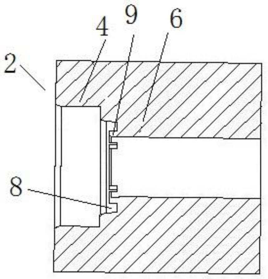
[0064] The difference between this embodiment and Embodiment 1 lies in that: in Embodiment 1, a jack segment 6 is provided on the second conductive member 2 , and a plug segment 7 is provided on the first conductive member 1 . And in this embodiment, if Figure 6 As shown, the second conductive member 2 is provided with a plug segment 7, the first conductive member 1 is provided with a socket segment 6, and the end of the second conductive member 2 plug segment 7 is provided with a bending piece 9, and the bending piece 9 An annular groove is provided on the radial inner side of the inner wall to form a fitting space 8 for the wedge block 5 to be installed. An annular slot 10 is provided on the inner wall surface of the insertion hole section 6 of the first conductive member 1. The first conductive member 1 is inserted into the An annular wedge mounting groove 11 is provided on the end surface of the hole segment 6 opposite to the plug segment 7 .

Embodiment 3

[0066] The difference between this embodiment and Embodiment 2 is that in Embodiment 2, a ring is provided on the end surface of the first conductive member 1 section of the first conductive member 1 opposite to the ring-shaped fitting space 8 on the second conductive member 2. The wedge mounting groove 11 is inserted for the rear side of the wedge block 5 when installed. And in this embodiment, if Figure 7 As shown, no wedge installation groove 11 is provided on the end surface of the first conductive part 1 section of the first conductive part 1 opposite to the annular fitting space 8 on the second conductive part 2. When connecting, the orientation of the first conductive part 1 The end surface of one side of the second conductive member 2 pushes the wedge block 5 into the fitting space 8 .


PUM


Abstract

The invention relates to the technical field of conductive assembly manufacturing, and provides a conductive assembly and a connecting structure between conductive members, the conductive assembly comprises a second conductive member and a first conductive member fixed to the end portion of the second conductive member, and one of the second conductive member and the first conductive member is provided with a plug segment. The other one is provided with a jack section for the insertion of the plug section; the conductive assembly also comprises a wedge block which is arranged between the plug section and the jack section along the axial direction of the second conductive member. A clamping groove is formed in the peripheral face of the plug section, contraction rings or a plurality of bent pieces arranged at intervals in the circumferential direction are arranged on the end faces, oppositely arranged when the plug section and the jack section are connected in an inserted mode, of the jack section, and the radial outer sides of the contraction rings or the bent pieces are provided with adaptive spaces for the wedge-shaped blocks to be inserted in. The wedge-shaped block is used for being pressed into the adaptive space by the plug section or the jack section opposite to the small end of the wedge-shaped block when the plug section and the jack section are connected in an inserted mode, and the contraction ring or the bending piece is bent through the inclined face and enters the clamping groove so as to form axial stopping with the clamping groove.

Description

technical field [0001] The invention relates to the technical field of manufacturing conductive components, in particular to a connection structure between conductive parts in a conductive component. Background technique [0002] At present, the conductive rod is generally welded by the joint and the rod body. The welding process is complicated, the manufacturing cost is high, and the noise, electromagnetic radiation and light radiation are relatively large during the welding process, and a lot of metal dust and smoke will be generated, which is harmful to the environment and work. affect the physical and mental health of personnel. [0003] The patent literature of CN111370876A in the prior art discloses a connection structure between a conductive rod and an electrical connection device. There is an insertion hole on the contact crimping deformation section, an annular protrusion is provided on the inner peripheral surface of the insertion hole, an insertion section is pro...

Claims


Application Information

Patent Timeline
IPC IPC(8): H01R4/20
CPCH01R4/20
Inventor 王红超李凯张元元李艳洁徐仲勋苑国旗李新刚司晓闯许东杰郭东方陆静井琼琼庞亚娟
Owner PINGGAO GRP
Why Eureka
Try Eureka