A tile laying and positioning brick jointer

A technology for brick joints and ceramic tiles, which is applied in the field of tile laying and positioning brick joints, can solve the problems of uneven corners and reduce work efficiency, and achieve the effect of preventing uneven corners and improving work efficiency.

Active Publication Date: 2020-07-17
瑞安市如果建材有限公司
View PDF4 Cites 0 Cited by
  • Summary
  • Abstract
  • Description
  • Claims
  • Application Information

AI Technical Summary

Problems solved by technology

[0002] When laying tiles, in order to avoid the occurrence of arching due to the different thermal expansion and contraction coefficients between the cement and the tile embryo body, seams must be left for paving. Nowadays, people generally use a small cross brick seam to install the tiles. For positioning and laying, the millimeters of the tiles are different, and the millimeters of the small cross brick seams are also different. In this way, not only can one tile be pasted at a time, but also when tiles with different millimeters are pasted, the small cross brick joints need to be replaced, reducing the Work efficiency, manual paving is prone to uneven corners

Method used


Image

  • A tile laying and positioning brick jointer
  • A tile laying and positioning brick jointer

Examples


Embodiment 1

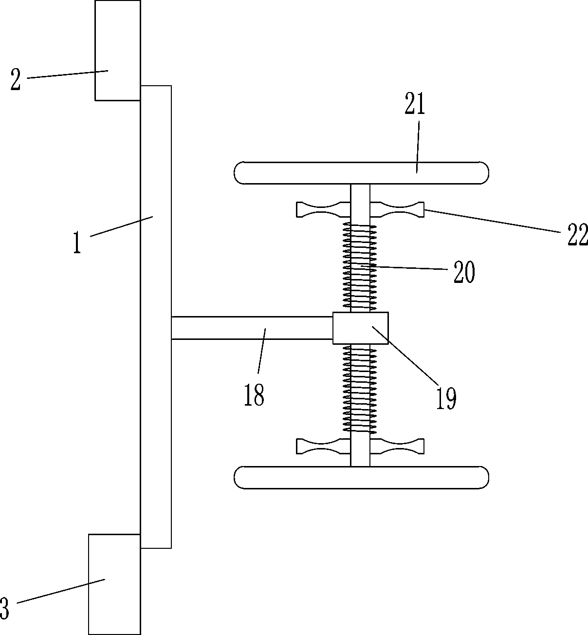
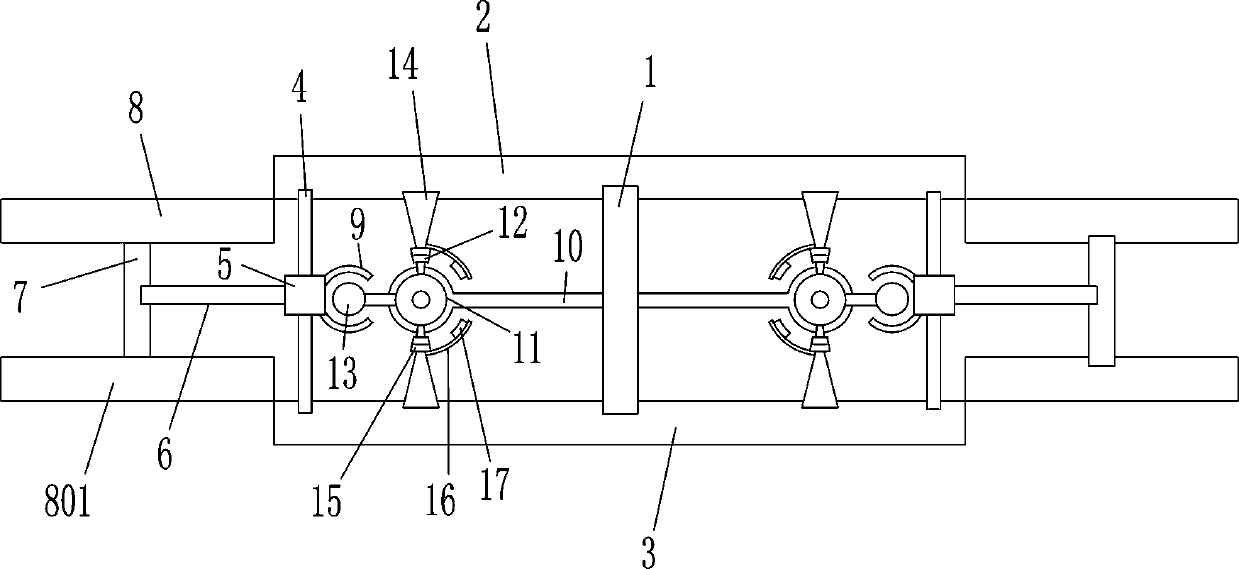
[0014] A tile laying and positioning brick jointer, such as Figure 1-2 As shown, including support plate 1, 2mm brick joint plate 2, 5mm brick joint plate 3, slide bar 4, sliding sleeve 5, cross bar 6, vertical bar 7, 2mm supplementary brick joint plate 8, 5mm supplementary Brick joint plate 801, arc sleeve 9, connecting plate 10, turntable 11, rotating magnet 12, swing ball 13, connecting block 14, middle limit magnet 15, arc rod 16 and upper and lower limit magnet 17, support The upper part of the rear side of the board 1 is connected with a 2mm brick joint board 2, the lower part of the rear side of the support plate 1 is connected with a 5mm brick joint board 3, and the front side of the 2mm brick joint board 2 and the 5mm brick joint board 3 is connected. There are two sliding rods 4, the two sliding rods 4 are symmetrical on the left and right, a sliding sleeve 5 is slidably connected to the sliding rod 4, a horizontal rod 6 is connected to the outer side of the sliding...

Embodiment 2

[0016] A tile laying and positioning brick jointer, such as Figure 1-2 As shown, including support plate 1, 2mm brick joint plate 2, 5mm brick joint plate 3, slide bar 4, sliding sleeve 5, cross bar 6, vertical bar 7, 2mm supplementary brick joint plate 8, 5mm supplementary Brick joint plate 801, arc sleeve 9, connecting plate 10, turntable 11, rotating magnet 12, swing ball 13, connecting block 14, middle limit magnet 15, arc rod 16 and upper and lower limit magnet 17, support The upper part of the rear side of the board 1 is connected with a 2mm brick joint board 2, the lower part of the rear side of the support plate 1 is connected with a 5mm brick joint board 3, and the front side of the 2mm brick joint board 2 and the 5mm brick joint board 3 is connected. There are two sliding rods 4, the two sliding rods 4 are symmetrical on the left and right, a sliding sleeve 5 is slidably connected to the sliding rod 4, a horizontal rod 6 is connected to the outer side of the sliding...


PUM


Abstract

The invention relates to a positioning brick seam device, in particular to a ceramic tile paving and positioning brick seam device. The to-be-solved technical scheme is to provide a ceramic tile paving and positioning brick seam device which can improve the work efficiency, can pave two ceramic tiles simultaneously, and can prevent the phenomenon of uneven four corners during ceramic tile paving.According to the technical scheme, the ceramic tile paving and positioning brick seam device comprises a supporting plate, a two-millimeter brick seam plate, a five-millimeter brick seam plate, a sliding rod, a sliding sleeve, a transverse rod, a vertical rod and the like; the upper portion of the rear side face of the supporting plate is connected with the two-millimeter brick seam plate, and thelower portion of the rear side face of the supporting plate is connected with the five-millimeter brick seam plate. The ceramic tile paving and positioning brick seam device has the advantages that through the two-millimeter brick seam plate and the five-millimeter brick seam plate, ceramic tile seams can be paved with two different ceramic tiles of two millimeters and five millimeters, and a two-millimeter supplement brick seam plate, a five-millimeter supplement brick seam plate, the two-millimeter brick seam plate and the five-millimeter brick seam plate can be adjusted to a same horizontal position by rotating turnplates on the left and right portions, thereby paving the two ceramic tiles simultaneously.

Description

technical field [0001] The invention relates to a positioning brick joint device, in particular to a ceramic tile laying positioning brick joint device. Background technique [0002] When tiling tiles, in order to avoid the arching of the cement and the tile body due to the different coefficients of thermal expansion and cold contraction, it is necessary to leave a seam for paving. Now, when laying tiles, people usually take a small cross tile jointer, and the tiles are installed. Positioning and paving, the millimeters of the tiles are different, and the millimeters of the corresponding small cross brick joints are also different, so that not only can only one tile be pasted at a time, but also when the tiles of different millimeters are pasted, the small cross brick joints need to be replaced, reducing the Work efficiency, manual paving is prone to uneven corners. SUMMARY OF THE INVENTION [0003] In order to overcome the disadvantage that people use a small cross brick...

Claims


Application Information

Patent Timeline
Patent Type & Authority Patents(China)
IPC IPC(8): E04F21/00
CPCE04F21/0092
Inventor 龙伟
Owner 瑞安市如果建材有限公司
Why Eureka
Try Eureka