Backlight module for providing light to a display panel and display device therewith

一种显示面板、背光模块的技术,应用在背光模块与其显示装置领域,能够解决拆装不便性、区域性亮暗不均、显示品质影响等问题,达到节省制造成本、亮暗不均热点的问题改善的效果

Active Publication Date: 2013-06-05
WISTRON CORP
View PDF5 Cites 11 Cited by
  • Summary
  • Abstract
  • Description
  • Claims
  • Application Information

AI Technical Summary

Problems solved by technology

[0003] In the existing edge-lit backlight module, if the distance between adjacent light-emitting diodes is represented by P, the distance from the light-emitting surface of the light-emitting diode to the visible area AA of the display panel projected to the light guide plate is represented by A, and the light-emitting surface of the light-emitting diode The ratio (A / P ratio) of the distance A projected from the visible area AA of the display panel to the light guide plate and the pitch P between adjacent light-emitting elements is related to the quality of the displayed image. Generally speaking, the larger the A / P ratio is, the better the display The better the luminous effect of the panel, and the smaller the A / P ratio, the display quality will be affected; that is, in the case of a higher A / P ratio, the light guide plate can provide a more uniform light source for the visible area AA of the display panel, while In the case of a low A / P ratio, the light source provided by the light guide plate will produce regional uneven brightness and darkness, resulting in hot spots (hot spots), thus reducing the display quality
However, based on considerations of cost, total power consumption, heat dissipation, and environmental protection, the number of light-emitting diodes must be reduced. Therefore, without changing the size of the panel, the pitch P of the light-emitting diodes will be relatively increased. However, if the possible size of the display panel is not reduced In the case of the viewing area AA, the distance A projected from the light-emitting surface of the light-emitting diode of the existing edge-lit backlight module to the visible area AA of the display panel to the light guide plate has been limited by the structural design and cannot be increased correspondingly, so it cannot Increasing the A / P ratio results in a decrease in display quality. If the distance A between the light-emitting surface of the light-emitting diode and the visible area AA of the display panel is projected to the light guide plate is lengthened, the structural design of the narrow frame cannot be achieved.
[0004] Furthermore, in terms of the assembly structure of traditional liquid crystal display devices, the optical material layer used to atomize and condense the light is installed on the upper surface of the light guide plate, and then the optical material layer and the light guide plate are fixed by pressing down with a plastic frame. Combination, because the optical material layer is in direct contact with the light guide plate, there will be scratches; and because the optical material layer is directly covered on the light guide plate, the light emitted by the light-emitting element will be due to the condensing effect of the prism. Inner concentration makes it easier to highlight the problem of hot spots. In this way, in order to cover hot spots with uneven brightness and darkness, the coverage area of ​​the plastic frame needs to overlap the visible area AA of the display panel, so it cannot be applied to the structural design of narrow bezels; Or, because the combination of the optical material layer and the light guide plate is fixed by pressing down the plastic frame, if the optical material layer needs to be reworked and replaced, the plastic frame must be disassembled, which will increase a lot of unnecessary man-hours and cause inconvenience in disassembly sex

Method used


Image

  • Backlight module for providing light to a display panel and display device therewith
  • Backlight module for providing light to a display panel and display device therewith
  • Backlight module for providing light to a display panel and display device therewith

Examples


Embodiment Construction

[0027] The aforementioned and other technical contents, features and effects of the present invention will be clearly presented in the following detailed description of preferred embodiments with reference to the accompanying drawings. The directional terms mentioned in the following embodiments, such as: up, down, left, right, front or back, etc., are only directions referring to the attached drawings. Accordingly, the directional terms are used to illustrate and not to limit the invention.

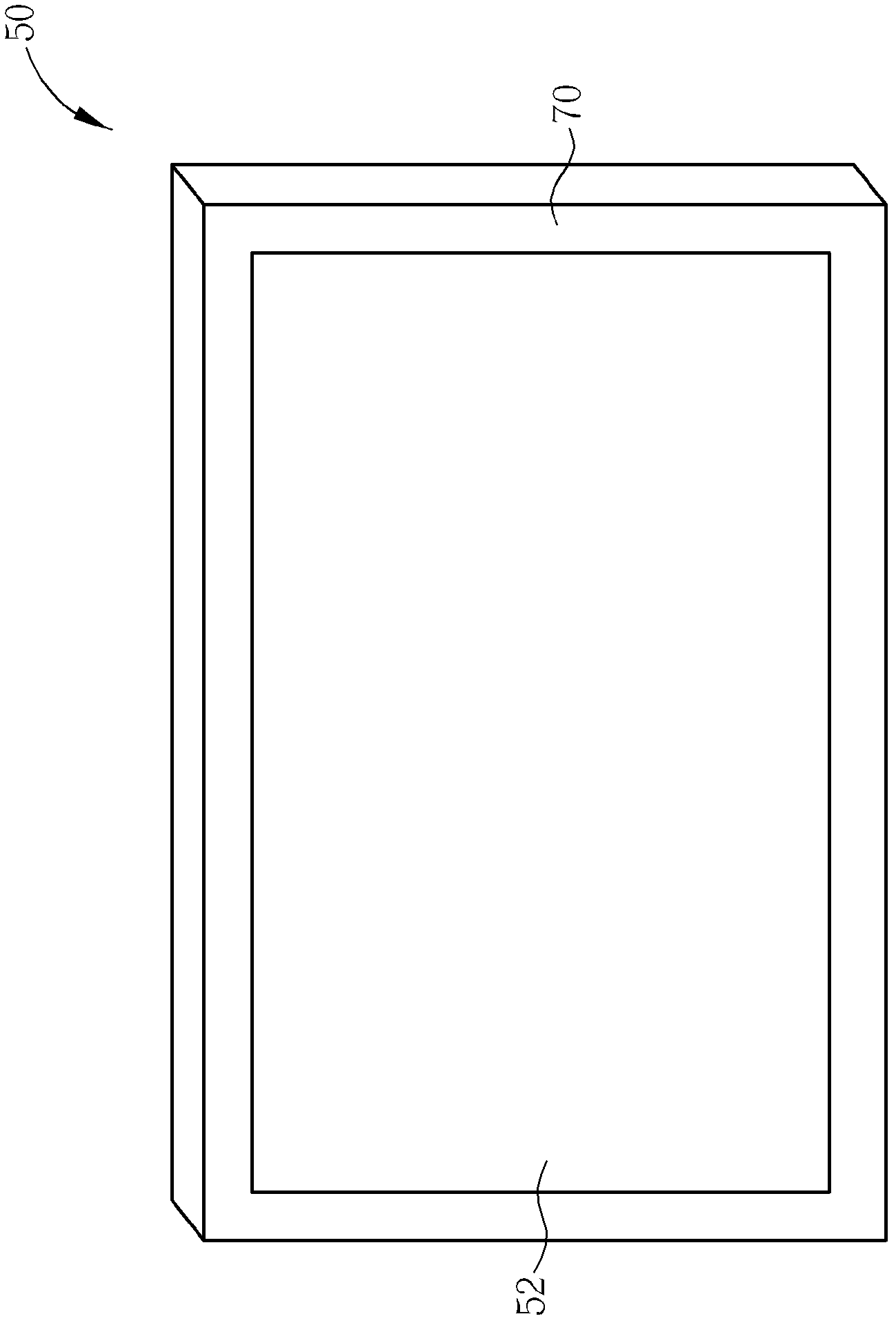
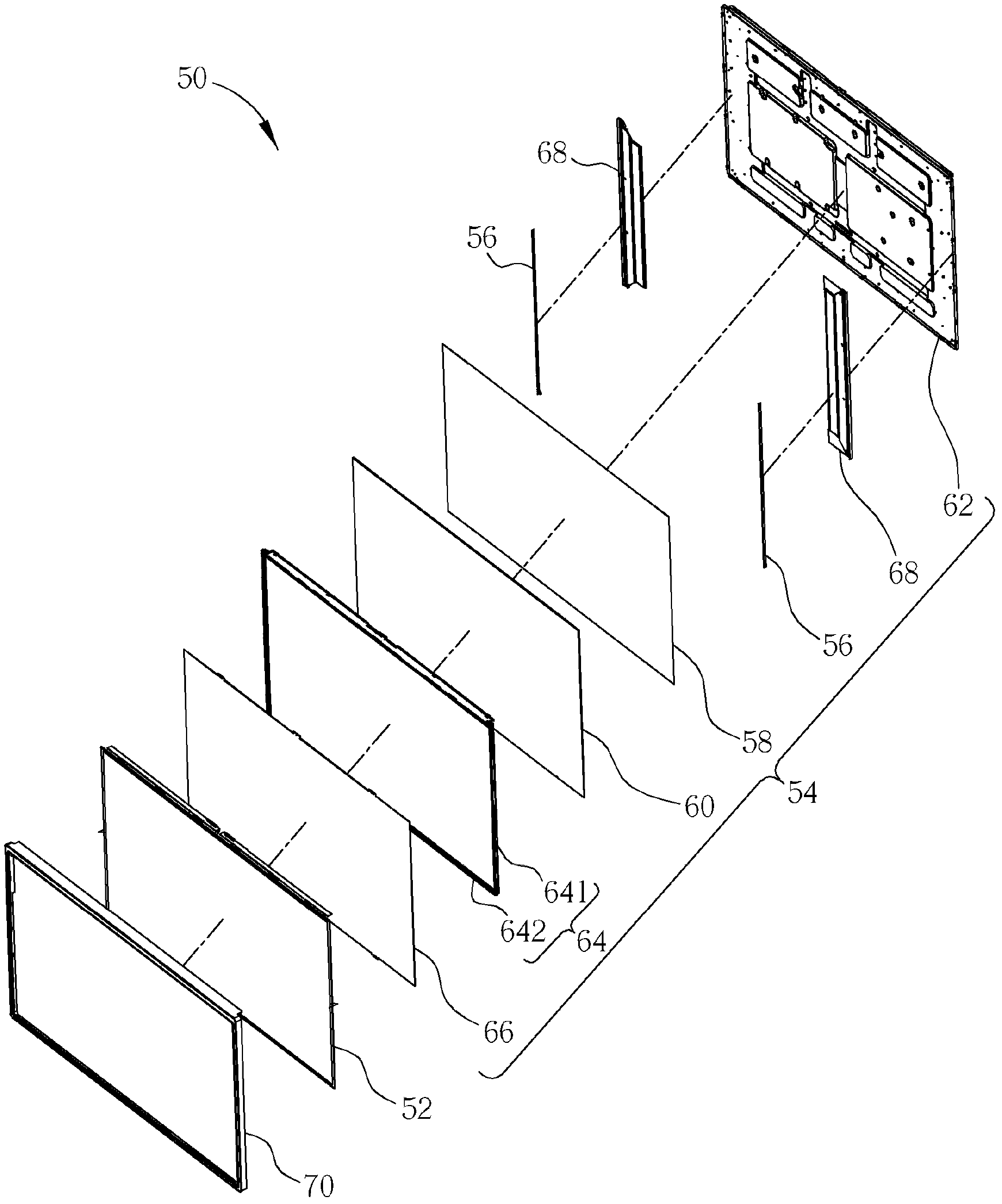
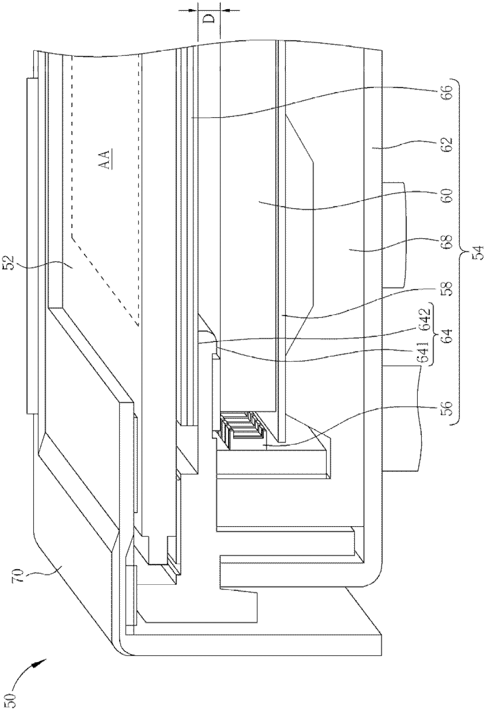
[0028] see figure 1 , Figure 2 to Figure 3 , figure 1 , Figure 2 to Figure 3 They are respectively an appearance schematic diagram, an exploded perspective view of components and a schematic cross-sectional diagram of the display device 50 according to Embodiment 1 of the present invention. The display device 50 can be a liquid crystal display or a liquid crystal display screen applied to a notebook computer. The display device 50 includes a display panel 52, which can be a liquid ...


PUM


Abstract

The present invention discloses a backlight module for providing light to a display panel and a display device therewith. The backlight module includes a light emitting unit for emitting light, a light guide plate disposed on a side of a display panel for guiding the light emitted by the light emitting unit to the display panel, a back cover installed outside the light emitting unit and the light guide plate, and a frame combined with the back cover for accommodating the light emitting unit and the light guide plate with the back cover. The frame includes a first side facing a surface of the light guide plate, and a second side opposite to the first side. The backlight module further includes an optical material layer disposed between the second side of the frame and the display panel for misting and focusing the light refracted from the light guide plate so as to provide uniform and bright light to the display panel.

Description

technical field [0001] The invention provides a backlight module and its display device for providing light source to a display panel, especially a backlight module and its display device with an optical material layer disposed between the frame and the display panel. Background technique [0002] With the rapid development of science and technology, thin, light, power-saving, and portable intelligent information products have filled the daily life space, and flat-panel display modules have also played a very important role in it. Among them, liquid crystal display devices have been widely used in portable information products such as notebook computers, personal digital assistants and mobile phones due to their light and thin appearance, low power consumption and no radiation pollution. It has a huge market share, and it has a tendency to replace CRT monitors of desktop computers and traditional TVs. Generally speaking, backlight modules can be divided into two types: side...

Claims


Application Information

Patent Timeline
Patent Type & Authority Applications(China)
IPC IPC(8): F21S8/00F21V17/00F21V13/02G02F1/13357F21Y101/02
CPCF21V13/02G02B6/0085G02B6/0088F21V17/00F21S8/00G02F1/133615
Inventor 郭盈德许俊升
Owner WISTRON CORP
Why Eureka
Try Eureka