Smooth transition of power-supply controller from first mode (pulse-frequency-modulation mode) to second mode (pulse-width-modulation mode)

A technology of power supply and inductor, which is applied in the direction of output power conversion device, adjustment of electric variable, data processing power supply, etc., and can solve the problem of sacrificing efficiency of boost converter 10, etc.

Active Publication Date: 2015-03-18
INTERSIL INC
View PDF6 Cites 7 Cited by
  • Summary
  • Abstract
  • Description
  • Claims
  • Application Information

AI Technical Summary

Problems solved by technology

Moreover, for a particular load, such a hysteresis band greater than required may cause the boost converter 10 to remain at a lower level due to a load level within the greater than required hysteresis band. efficiency mode at the expense of efficiency

Method used


Image

  • Smooth transition of power-supply controller from first mode (pulse-frequency-modulation mode) to second mode (pulse-width-modulation mode)
  • Smooth transition of power-supply controller from first mode (pulse-frequency-modulation mode) to second mode (pulse-width-modulation mode)
  • Smooth transition of power-supply controller from first mode (pulse-frequency-modulation mode) to second mode (pulse-width-modulation mode)

Examples


Embodiment Construction

[0223] refer to Figure 5-7 , according to an embodiment a boost converter and technique for alleviating at least the first problem described above is described.

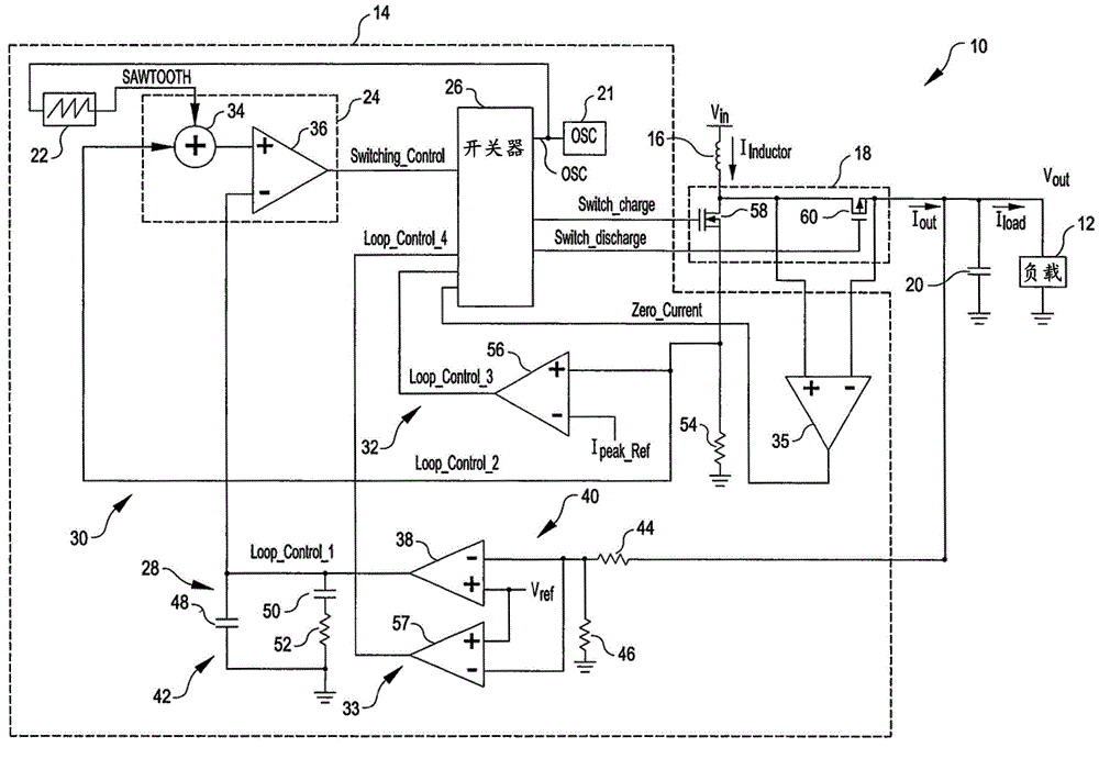
[0224] Figure 5 is a diagram of a boost converter 70 configured according to an embodiment to balance at least one of its parts (eg, a control loop) so that after transitioning from a PFM mode to a discontinuous PWM mode ,Compared to figure 1 The boost converter 10, V out is the momentary amplitude change that is subjected to little or no transition, or at least a reduced transition.

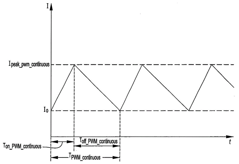
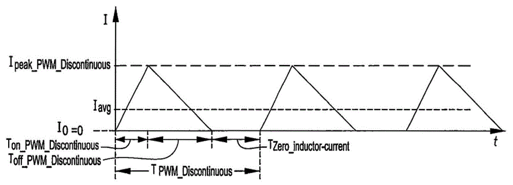
[0225] Image 6 is an inductor current I during a PFM mode just before transitioning to a discontinuous PWM mode according to an embodiment Inductor (t) 72 versus time, and an inductor current I during a discontinuous PWM mode just after transitioning from the PFM mode Inductor (t) 74 graph versus time.

[0226] and Figure 7 is the Image 6 The graph then adds a virtual discontinuous PWM inductor current I Inductor (t) 76 ...


PUM


Abstract

In an embodiment, a power-supply controller includes switching circuitry and an adjuster circuit. The switching circuitry is configured to cause a charging current to flow until the charging current has a predetermined relationship to a threshold, and to cause a discharging current to flow to an output node that carries an output voltage after the charging current. And the adjuster circuit is configured to adjust the threshold such that a ripple voltage superimposed on the output voltage has an approximately constant magnitude. For example, a power supply may include such a power-supply controller to maintain the magnitude of the output ripple voltage within a particular range during a pulse-frequency-modulation (PFM) mode despite variations in one or more parameters such as input voltage, output voltage, filter capacitance, phase inductance, and charging-current-sense impedance, from their respective nominal values.

Description

[0001] priority claim [0002] This application claims priority to U.S. Provisional Patent Application No. 61 / 922,259, filed December 31, 2013, and U.S. Provisional Patent Application No. 61 / 874,351, filed September 5, 2013; are hereby incorporated by reference in their entirety. technical field [0003] The present application relates generally to electronic circuits, and an embodiment disclosed in the present application relates particularly to a device configured to maintain the ripple of an output voltage within a specified range, such as a substantially constant The level of the controller of the power supply. Background technique [0004] figure 1 is a circuit diagram of a power supply, here a boost converter (sometimes referred to as a boost regulator) 10, and a load 12 receiving power from the boost converter. The boost converter 10 converts an input signal (here an input voltage V in ) becomes a regulated output signal (here a regulated output voltage V out ), ...

Claims


Application Information

Patent Timeline
Patent Type & Authority Applications(China)
IPC IPC(8): H02M3/158H02M1/00
CPCH02M3/157G06F1/26H02M2001/0032G09G3/3696H02M2001/0025H02M1/14H02M3/156H02M3/1588H02M1/0025H02M1/0032Y02B70/10
Inventor 尼可拉斯·亚曲柏德
Owner INTERSIL INC
Why Eureka
Try Eureka