Vehicle brake force generation device

A technology for generating device and braking force, which is applied in the direction of braking action starting device, electric device, brake, etc., which can solve the problems of sudden change of braking feeling, discomfort, power reduction, etc., and achieve the effect of improving the stability of behavior

Active Publication Date: 2015-03-18
HONDA MOTOR CO LTD
View PDF8 Cites 3 Cited by
  • Summary
  • Abstract
  • Description
  • Claims
  • Application Information

AI Technical Summary

Problems solved by technology

[0015] However, in the braking force control technique disclosed in Patent Document 1, if the diagnostic result of the ABS device is abnormal, the regenerative braking control of the wheel drive motor is immediately prohibited, which may cause regenerative braking to the driver. Uncomfortable braking feeling caused by a sudden change in braking force caused by sudden stop of braking control, and the power obtained by regenerative braking will decrease

Method used


Image

  • Vehicle brake force generation device
  • Vehicle brake force generation device
  • Vehicle brake force generation device

Examples


Embodiment Construction

[0035] Hereinafter, a vehicle braking force generator according to an embodiment of the present invention will be described in detail with reference to the drawings.

[0036] (An example of application of the vehicle braking force generator 11 according to the embodiment of the present invention to an electric vehicle V)

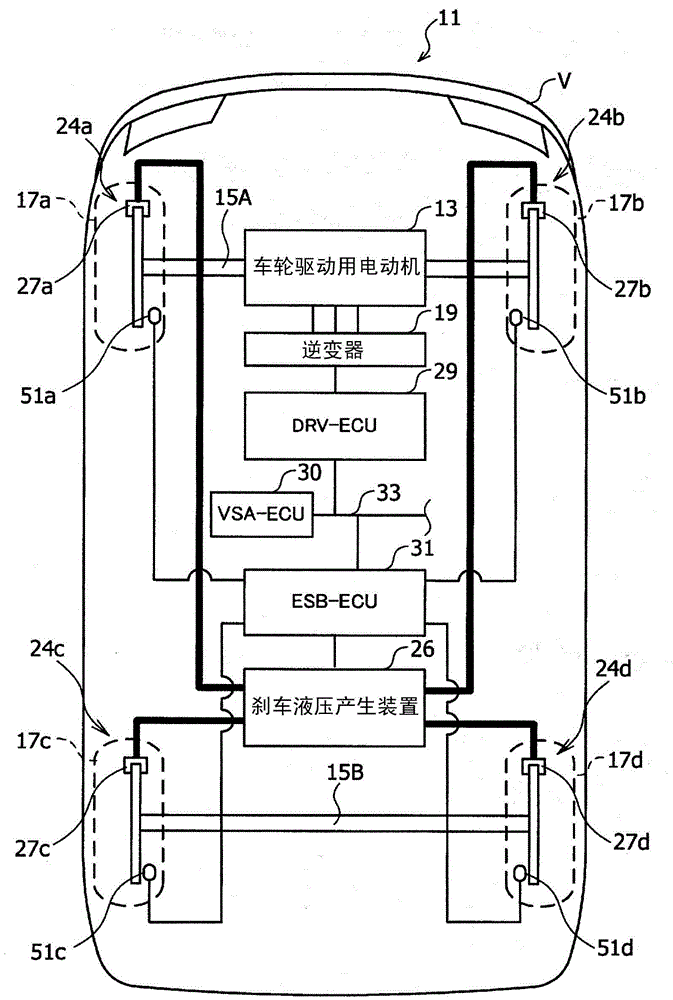
[0037]First, for an example of application of the vehicle braking force generator 11 according to the embodiment of the present invention to an electric vehicle V, refer to figure 1 Be explained. figure 1 It is a diagram showing an example in which the vehicle braking force generator 11 according to the embodiment of the present invention is applied to an electric vehicle V. As shown in FIG.

[0038] Prior to the description of the embodiments of the present invention, additional rules for symbols employed for convenience of description will be mentioned. Since the vehicle braking force generator 11 according to the embodiment of the present invention is m...


PUM


Abstract

A vehicle brake force generation device (11) is provided with an electric motor (13) for applying drive force and regenerative brake force to the wheels (17) of an electric vehicle (V), a brake hydraulic pressure generation device (26) for generating the brake hydraulic pressure to be applied to the calipers (27) of the electric vehicle (V), a slip information computation unit (63) for computing the slip information of the wheels (17), a VSA device (18) for controlling the friction braking of at least the brake hydraulic pressure generation device (26) such that the slipping of the wheels (17) is inhibited, a first diagnosis unit (67) for diagnosing the VSA device (18), and a brake control unit (65) for controlling the cooperative braking which includes controlling the regenerative braking of the electric motor (13) and/or controlling the friction braking of the brake hydraulic pressure generation device (26). The brake control unit (65) continues to control the regenerative braking of the electric motor (13) when a behavior stabilization assistance device (18) goes into an abnormal state while the regenerative braking of the electric motor (13) is being controlled.

Description

technical field [0001] The present invention relates to a braking force generator for a vehicle that generates braking force for a vehicle. Background technique [0002] For example, in a hybrid vehicle, not only a conventional brake device that generates a braking force through a hydraulic circuit but also a By-Wire type brake device that generates a braking force through an electric circuit is used. In this drive-by-wire brake device, an operation amount of a brake pedal by a driver is converted into an electric signal, and supplied to an electric motor that drives a piston of a slave cylinder (hereinafter referred to as "electric servo brake device"). In this way, the motor compresses and drives the piston to generate brake hydraulic pressure in the electric servo brake device, and the wheel cylinder (wheel cylinder) is operated according to the brake hydraulic pressure thus generated to generate friction-based braking force. [0003] In such a drive-by-wire brake device...

Claims


Application Information

Patent Timeline
Patent Type & Authority Applications(China)
IPC IPC(8): B60T8/17B60T17/18
CPCB60T8/1755B60T2270/402B60T2270/604B60L3/108B60L7/26B60L15/2009B60L7/18B60T7/042Y10S903/947Y02T10/72B60T8/17616
Inventor 赤峰宏平植野真之
Owner HONDA MOTOR CO LTD
Why Eureka
Try Eureka