An insecticidal lamp with the functions of power saving and automatic removal of pest corpses

An automatic removal and insecticidal lamp technology, which is applied in the device, application, animal husbandry and other directions of catching or killing insects, can solve the problems of short service life, power consumption and high use cost, and achieve long service life and low manufacturing cost. , the effect of low cost of use

Inactive Publication Date: 2016-08-31
CHONGQING LIZHENYUAN AGRI & FORESTRY TECH
View PDF12 Cites 0 Cited by
  • Summary
  • Abstract
  • Description
  • Claims
  • Application Information

AI Technical Summary

Problems solved by technology

[0003] Existing insecticidal lamps have the following defects: 1. Because the light source of existing insecticidal lamps adopts conventional black light tubes or LED lamps, although black light tubes are cheap, their service life is short and the use cost of the whole life is high; Although the lamp has a long service life, the unit price is expensive
Moreover, the common disadvantage of these two lights is that they need electricity, which not only consumes electric energy, but also leads to high use costs, and it is also troublesome to solve the power supply in remote mountainous areas.
[0004] 2. Since the dead insects contain protein, they will stick to the electric grid of the high-voltage electric grid after death. After a long time, it will affect the insecticidal efficiency, and even make the high-voltage electric grid unable to work normally. Therefore, it is urgent to solve the above technical problems

Method used


Image

  • An insecticidal lamp with the functions of power saving and automatic removal of pest corpses
  • An insecticidal lamp with the functions of power saving and automatic removal of pest corpses
  • An insecticidal lamp with the functions of power saving and automatic removal of pest corpses

Examples


Embodiment Construction

[0019] Below in conjunction with accompanying drawing and embodiment the present invention will be further described:

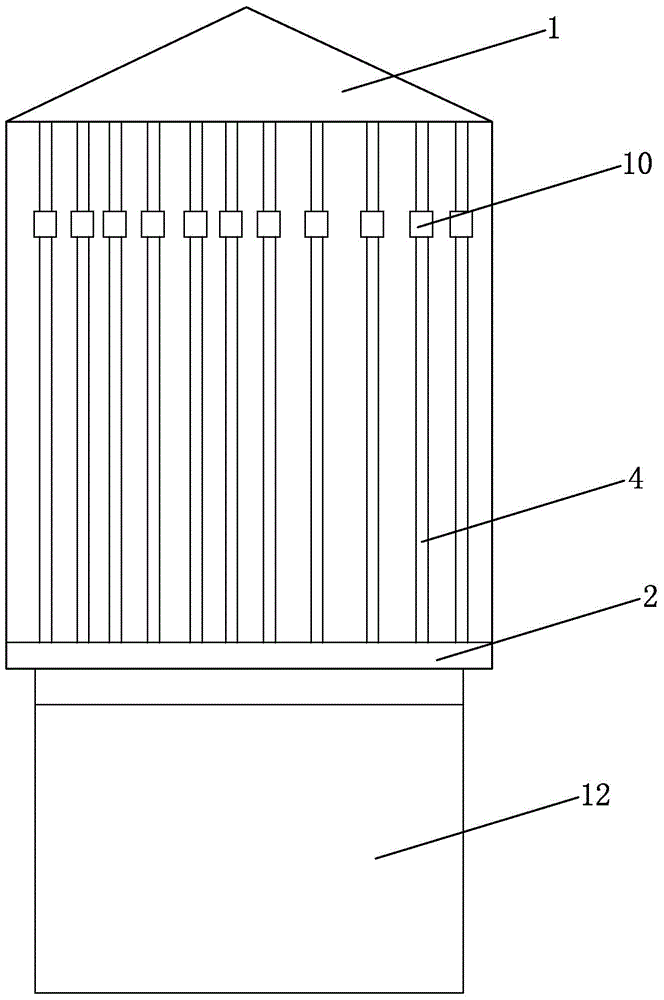
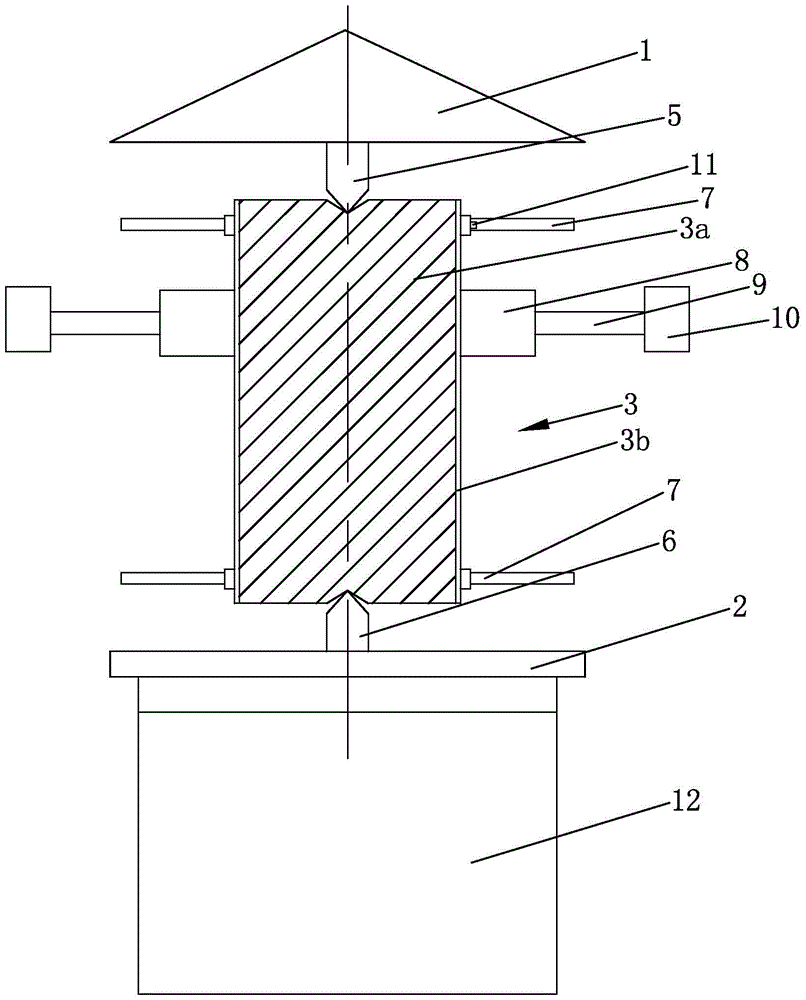
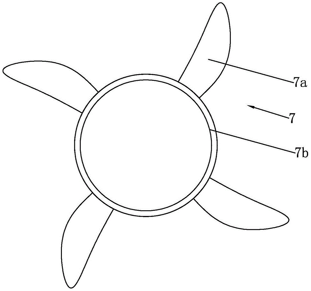
[0020] Such as figure 1 , 2 As shown in , 3, a kind of insecticidal lamp with the function of saving electricity and automatically removing pest corpses is mainly composed of a lamp cap 1, an insect collecting tray 2, a light source 3, a high-voltage electric grid 4, an upper top 5, a lower top 6, Windmill 7, nut 8, connecting rod 9, sliding sleeve 10, radial screw 11 and insect collecting bottle 12 constitute. Wherein, the lamp cap 1 adopts the existing structure, and the top surface of the lamp cap 1 is provided with a hook, and the present invention can be hung on a column through the hook. A light source 3 and a high-voltage electric grid 4 are fixedly connected between the lamp cap 1 and the insect collecting tray 2, wherein the electric grid 4a of the high-voltage electric grid 4 is distributed on the same cylinder, and the high-voltage electric grid ...


PUM


Abstract

The invention discloses a pest-killing lamp with a power saving function and a function of automatic removal of dead pests. A lamp source and a high-tension electric grid are fixed between a lamp cap and a pest collecting tray. The lamp source is composed of a lamp post and a fluorescent coating. Center holes in upper and lower end faces of the lamp post are in rotatable fit with an upper center and a lower center. The fluorescent coating is provided on a whole external-threaded hole of the lamp post. The lamp post is fixedly sleeved with two pinwheels. A nut sleeves the lamp post between the pinwheels and is fixedly connected with a sliding sleeve through a connecting rod; the sliding sleeve is in sliding fit with the high-tension electric grid. The lamp source structure of the pest-killing lamp is totally different from a black lamp tube or an LED lamp; the pest-killing lamp emits light by means of absorption of sunlight, and the lamp source consumes no electricity; the pest-killing lamp has long service life; the pinwheels are driven by natural wind, thus the whole peripheral surface of the fluorescent coating is evenly heated; the lamp post is driven by the pinwheels to move and also drives the sliding sleeve to move, thus the dead pests attaching to the high-tension electric grid are automatically removed.

Description

technical field [0001] The invention belongs to the field of agricultural pest control, in particular to an insecticidal lamp. Background technique [0002] With the development of green agriculture, insecticidal lamps have been widely used. Existing insecticidal lamps mainly include a light source and a high-voltage grid, wherein the light source emits light to attract the pests by using their phototaxis, and kill the pests through the high-voltage grid. At the same time, the light source now uses conventional black light tubes or LED lights. [0003] Existing insecticidal lamps have the following defects: 1. Because the light source of existing insecticidal lamps adopts conventional black light tubes or LED lamps, although black light tubes are cheap, their service life is short and the use cost of the whole life is high; Although the lamp has a long service life, the unit price is expensive. Moreover, the common disadvantage of these two kinds of lamps is that they nee...

Claims


Application Information

Patent Timeline
Patent Type & Authority Patents(China)
IPC IPC(8): A01M1/04A01M1/22
Inventor 龚恒翔朱国军喻小华
Owner CHONGQING LIZHENYUAN AGRI & FORESTRY TECH
Why Eureka
Try Eureka