Cross-flow filter device and filter assembly for cross-flow filter device

A technology for cross-flow filtration and filter components, which is applied in the fields of filtration and separation, fixed filter element filters, chemical instruments and methods, etc., can solve the problems of poor sealing reliability, inability to accurately determine the leaking parts of filter components, and low sealing reliability.

Active Publication Date: 2016-04-06
CHENGDU INTERMENT TECH
View PDF6 Cites 0 Cited by
  • Summary
  • Abstract
  • Description
  • Claims
  • Application Information

AI Technical Summary

Problems solved by technology

[0003] In the actual production and use of the above-mentioned cross-flow filter device and cross-flow filter assembly, the inventor found the following problems: 1. Since the upper end joint 13 and the lower end joint 14 are integral structures, when the filter assembly is assembled, the upper end joint 13 or the lower end joint 14 must be bonded to the inner filter tube 8 and the outer filter tube 9 at the same time, resulting in inconvenient glue application, unable to observe the bonding state of the inner filter tube 8, the bonding of the inner filter tube 8 is prone to failure, and the sealing reliability is low. It is also impossible to accurately judge the air leakage part of the filter assembly during the air tightness test after assembly
2. Due to processing and manufacturing reasons, it is impossible to ensure that the two ends of all filter components can be in contact with the counterbore end faces on the pressure plate 15 and the baffle plate 16 in the installation method of the filter components in the above-mentioned cross-flow filter device, so the filter There is axial series movement in the whole assembly, and the sealing reliability is poor

Method used


Image

  • Cross-flow filter device and filter assembly for cross-flow filter device
  • Cross-flow filter device and filter assembly for cross-flow filter device
  • Cross-flow filter device and filter assembly for cross-flow filter device

Examples


Embodiment Construction

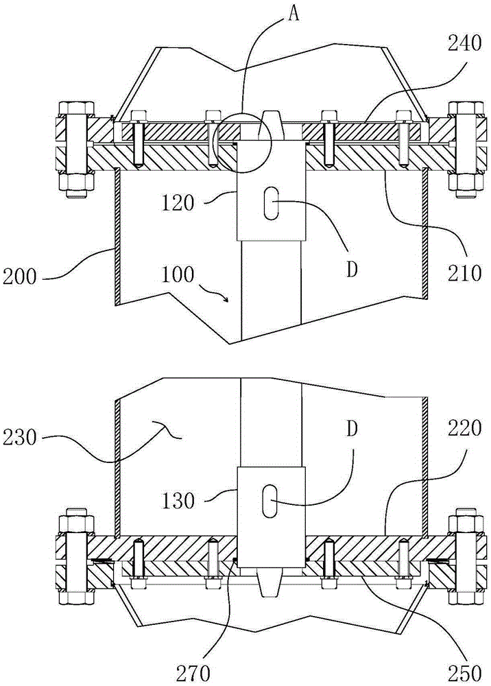
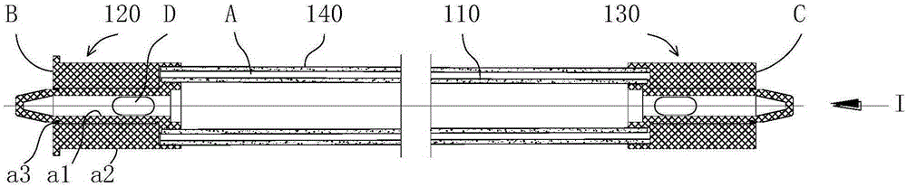
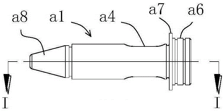
[0020] Such as Figure 2-7 As shown, the filter assembly includes an inner filter tube 110 and an outer filter tube 140 that is sleeved on the outside of the inner filter tube 110 and maintains a relative position with the inner filter tube 110 through an upper end joint 120 and a lower end joint 130. The channel A to be filtered is formed between the inner tube walls of the outer filter tube 140, the upper joint 120 is provided with an unfiltered output channel B which is connected to one end of the channel A to be filtered, and the lower joint 130 is provided with a The other end of the filter channel A is connected to the input channel C to be filtered. The upper joint 120 and the lower joint 130 are respectively provided with the inner filter tube 110 lumen and are used to export the filtered matter in the lumen to the inner filter tube 110. The filtered material output channel D of the filter assembly, the upper end joint 120 and the lower end joint 130 respectively have ...


PUM


Abstract

The invention discloses an improved cross flow filtering device and a filtering assembly used for the same to optimize the mounting sealing performance of the filtering assembly in the cross flow filtering device. The cross flow filtering device comprises a shell and a filtering assembly positioned in the shell, wherein an annular shoulder positioned above an upper pore plate in the shell is arranged on the peripheral wall of an upper end connector of the filtering assembly; an annular sealing element is arranged between a step surface of the bottom of the annular shoulder and the top surface of the upper pore plate; and a pressing mechanism, which presses a step surface at the top of the annular shoulder downwards to ensure that the step surface of the bottom of the annular shoulder squeezes the annular sealing element downwards, is arranged at the top surface of the upper pore plate. The mounting manner of the filtering assembly ensures axial positioning of the filtering assembly, and by combining with the annular sealing component which is arranged between the step surface of the bottom of the annular shoulder and the top surface of the upper pore plate and is deformed by virtue of axial extrusion, the sealing reliability is greatly improved.

Description

technical field [0001] The invention relates to a cross-flow filter device and a filter assembly for the cross-flow filter device. Background technique [0002] The patent application publication number CN101869786A filed by the applicant of the present invention describes a cross-flow filter assembly, which includes an inner filter tube 8 and is sleeved on the outside of the inner filter tube 8 and passes through an upper end joint 13 and a lower end joint 14. The outer filter tube 9 that keeps the relative position with the inner filter tube 8, the channel 10 to be filtered is formed between the outer tube wall of the inner filter tube 8 and the inner tube wall of the outer filter tube 9, and the upper end joint 13 is provided with a The upper end of the channel 10 is connected to the unfiltered material output channel, the lower end joint 14 is provided with the to-be-filtered material input channel 5 that is connected to the lower end of the to-be-filtered material chann...

Claims


Application Information

Patent Timeline
Patent Type & Authority Patents(China)
IPC IPC(8): B01D29/35
Inventor 高麟汪涛樊彬
Owner CHENGDU INTERMENT TECH
Why Eureka
Try Eureka