Blanking device for centrifuge

A centrifuge and feeding tube technology, applied in the centrifuge and other directions, can solve the problems of dryer or silo blockage, inconvenient adjustment, uneven discharge, etc., and achieve the effects of improving sealing, convenient cleaning, and reducing wear

Inactive Publication Date: 2015-03-25
HUNAN XIANGHENG SALT CHEM
View PDF6 Cites 2 Cited by
  • Summary
  • Abstract
  • Description
  • Claims
  • Application Information

AI Technical Summary

Problems solved by technology

The washing water switching device of the piston pusher centrifuge has a complex structure, although the washing water existing in the unloading and washing of the piston pusher centrifuge will enter the dryer or silo along the discharge port, causing the dryer or silo to be blocked However, there are still problems such as uneven discharge and inconvenient adjustment of the discharge position.

Method used


Image

  • Blanking device for centrifuge
  • Blanking device for centrifuge
  • Blanking device for centrifuge

Examples


Embodiment 1

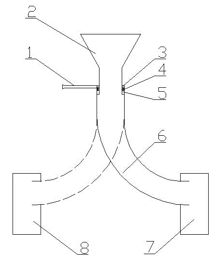
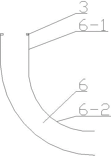
[0023] refer to figure 1 , image 3 with Figure 4 , a centrifuge blanking device, comprising a hopper 2, a blanking tube 6, a blanking tube fixing mechanism, a position adjustment handle 1, a sealing ring 4, a first discharge cylinder 7 and a second discharge cylinder 8; The upper end of the feeding pipe 6 is movably connected to the lower end of the hopper 2 through the fixing mechanism of the feeding pipe; the joint between the feeding pipe 6 and the hopper 2 is provided with a sealing ring 4; The adjustment handle 1 of the feeding pipe 6; the feeding pipe 6 is composed of a circular steel pipe 6-1 and an arc-shaped hose 6-2; the end of the arc-shaped hose 6-2 is located at the first discharge barrel 7 or in the second discharge barrel 8, so that the material in the curved hose 6-2 enters the first discharge barrel 7 or the second discharge barrel 8 at a tangent; the first discharge barrel 7 or the second discharge barrel A notch 7-1 for placing an arc-shaped hose 6-2 is...

Embodiment 2

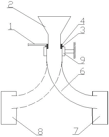
[0028] refer to Figure 2~4 , a centrifuge blanking device, comprising a hopper 2, a blanking tube 6, a blanking tube fixing mechanism, a position adjustment handle 1, a sealing ring 4, a first discharge cylinder 7 and a second discharge cylinder 8; The upper end of the feeding pipe 6 is movably connected to the lower end of the hopper 2 through the fixing mechanism of the feeding pipe; the joint between the feeding pipe 6 and the hopper 2 is provided with a sealing ring 4; The adjustment handle 1 of the feeding pipe 6; the feeding pipe 6 is composed of a circular steel pipe 6-1 and an arc-shaped hose 6-2; the end of the arc-shaped hose 6-2 is located at the first discharge barrel 7 or in the second discharge barrel 8, so that the material in the curved hose 6-2 enters the first discharge barrel 7 or the second discharge barrel 8 at a tangent; the first discharge barrel 7 or the second discharge barrel A notch 7-1 for placing an arc-shaped hose 6-2 is provided on the side wal...


PUM


Abstract

The invention discloses a blanking device for a centrifuge. The blanking device comprises a receiving hopper, a blanking pipe, a blanking pipe fixing mechanism, a positioning handle, a sealing ring and discharging barrels, wherein the upper end of the blanking pipe is movably connected with the lower end of the receiving hopper through the blanking pipe fixing mechanism; the sealing ring is arranged at a joint of the blanking pipe and the receiving hopper; the positioning handle for rotating the blanking pipe is fixedly connected to the upper end of the blanking pipe; the blanking pipe consists of a circular steel pipe and an arc-shaped hose; the tail end of the arc-shaped hose is positioned in one discharging barrel, so that materials in the arc-shaped hose tangentially enter the discharging barrel; nicks for placing the arc-shaped hose are formed in the sidewalls of the discharging barrels. According to the blanking device for the centrifuge, the blanking position and range can be conveniently, rapidly and flexibly switched, the discharging impact is reduced, and the uniform distribution of the materials is facilitated.

Description

technical field [0001] The invention relates to a part of a centrifuge, in particular to a centrifuge unloading device. Background technique [0002] At present, the unloading device of the centrifuge generally uses a pipeline to directly unload the material through the collection port to the conveying equipment such as the belt, and then enters the dryer. First of all, when the centrifuge needs to be cleaned, since the feeding pipe cannot rotate, the centrifuge and subsequent process equipment (such as the conveyor belt) must stop working, otherwise a large amount of water will be brought into the conveyor belt below the feeding pipe, making it impossible to Normal operation, and the cleaning water cannot be effectively collected; secondly, if the centrifuge fails, it will cause wet materials to enter the dryer because it cannot be processed in a timely and effective manner. In addition, the unloading position of the unloading device is too concentrated, resulting in uneve...

Claims


Application Information

Patent Timeline
Patent Type & Authority Applications(China)
IPC IPC(8): B04B11/00
Inventor 曾华明张谷丰李伟
Owner HUNAN XIANGHENG SALT CHEM
Why Eureka
Try Eureka