Automatic cutter deformation regulating device for ultra-large plate shearing machine

A technology of cutting tool deformation and automatic adjustment, applied in the direction of shearing devices, shearing machine accessories, manufacturing tools, etc., can solve the problems of large manual adjustment errors, inability to achieve flexible feeding, heavy workload, etc., and achieve the goal of operation Increased accuracy, accelerated blade deformation, and long service life

Inactive Publication Date: 2015-03-25
JIANGSU UNIV
View PDF11 Cites 7 Cited by
  • Summary
  • Abstract
  • Description
  • Claims
  • Application Information

AI Technical Summary

Problems solved by technology

The disadvantage of the trolley is that the telescopic oil cylinder is used as the driving force of the trolley, which leads to inaccurate positioning of the trolley. At the same time, the trolley uses an I-shaped track, which causes the trolley to move left and right on the track, often deviates, and cannot completely realize straight-line driving
[0005] At this stage, most of the feeding mechanisms are rigid feeding, and the feeding distance cannot be changed after the mechanism feeding is completed.
Common machine tool platforms are fed by screw nuts and dovetail guide rails. The position accuracy is high but the feeding distance is fixed, which cannot meet the requirements of flexible feeding.
[0006] To sum up, the current ultra-large shearing machine lacks an automatic adjustment device and method for blade deformation, and the manual adjustment method for blade deformation has obvious defects: 1. The length of the cutter is relatively large, and there are many top and pull adjustment bolts that need to be adjusted. Workers need to adjust one by one and use feeler gauges to calibrate, the workload is heavy
2. It takes a long time to manually adjust once, which seriously prolongs the idle time of the equipment and makes the production efficiency low
3. Manual adjustment error is large

Method used


Image

  • Automatic cutter deformation regulating device for ultra-large plate shearing machine
  • Automatic cutter deformation regulating device for ultra-large plate shearing machine
  • Automatic cutter deformation regulating device for ultra-large plate shearing machine

Examples


Embodiment Construction

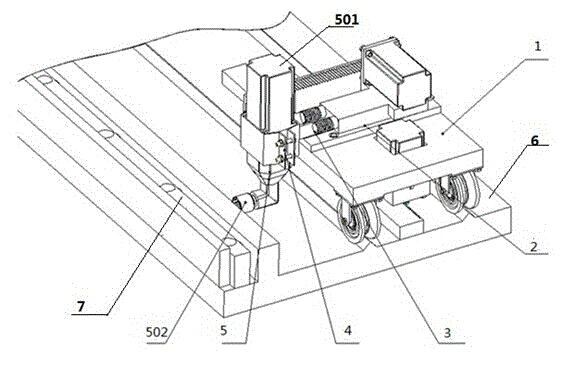
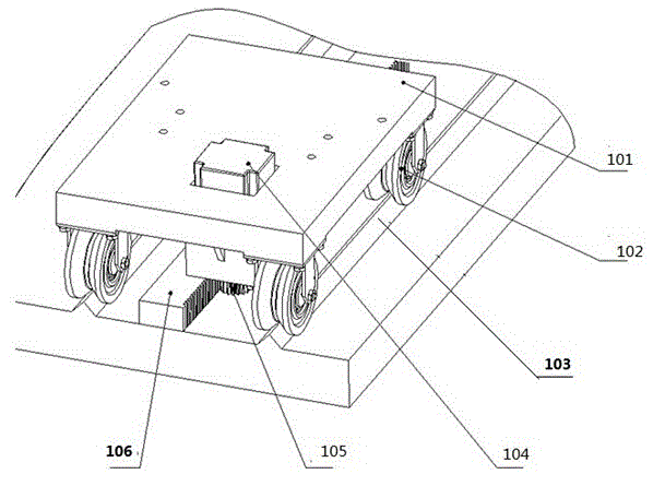
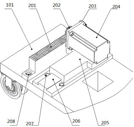
[0022] like figure 1 As shown, the automatic adjustment device for the deformation amount of the super large shearing machine tool of the present invention includes a rail car 1, a wrench feeding mechanism 2, a wrench connecting mechanism 3, a clamping device 4, a wrench mechanism 5, a feeding platform 6 and a tool deformation amount top, Pull bolt assembly 7.

[0023] like figure 1 and 2 As shown, the rail car 1 includes a car body 101, four V-shaped sheaves 102, two V-shaped guide rails 103, a car body servo motor 104, a car body drive spur gear 105 and a car body drive rack 106; the The bottom of the vehicle body 101 is provided with four bosses, the four V-shaped sheaves 102 are respectively fixed on the four said bosses by bolts, and the four said V-shaped sheaves 102 are installed symmetrically in pairs; The body 101 is further provided with a sunken platform, and the body servo motor 104 is fixed on the sunken platform; the body servo motor 104 is coaxially connected...


PUM


Abstract

The invention discloses an automatic cutter deformation regulating device for an ultra-large plate shearing machine. The automatic cutter deformation regulating device comprises a rail trolley, a feeding mechanism, spanner connecting mechanisms, a clamping mechanism and a spanner mechanism. V-shaped sheaves are adopted in the rail trolley so as to be matched with V-shaped guide rails, it is guaranteed that the trolley is operated smoothly, and meanwhile the trolley can not be disengaged from the rails or swing when receiving force perpendicular to the moving direction; gear and rack engagement is used for the rail trolley, servo motors are used for providing driving force, and localization of the walking direction of the rail trolley in the operation process is accurately controlled; the spanner feeding mechanism is used for feeding and retracting the spanner mechanism, the feeding mechanism receives force flexibly, and a sleeve of the spanner mechanism can be engaged with a regulating bolt under the condition that the spanner servo motor is ignited. According to the automatic cutter deformation regulating device, based on the fact that manual regulation is eliminated, regulation of the blade deformation can be greatly accelerated, and therefore work efficiency and operation accuracy are improved to a great extent.

Description

technical field [0001] The invention relates to an automatic adjustment device for tool deformation, in particular to an automatic adjustment device for tool deformation of a super-large shearing machine. Compensation for shear edge deformation. technical background [0002] When the shearing machine is under the shearing action of the upper and lower blades, it is jointly affected by the internal stress of the plate, the upper and lower and front and rear shearing forces, and the shear plastic elastic deformation. When the deformation exceeds the allowable error range, it takes time and effort to correct and straighten the curve. Therefore, it is necessary to detect the deformation curve of the shearing edge of the sheet metal, and to compensate for the deformation of the shearing edge of the sheet metal by pre-estimating and adjusting the deformation of the tool edge. At present, the adjustment of the tool deformation is completely done manually. The socket wrench is use...

Claims


Application Information

Patent Timeline
Patent Type & Authority Applications(China)
IPC IPC(8): B23D33/00
Inventor 李伯全史伟超张西良徐桢英任乃飞任旭东王匀谢方伟王存堂
Owner JIANGSU UNIV
Why Eureka
Try Eureka