
A lifting helical gear processing equipment

A technology for processing equipment and helical gears, which is applied in metal processing equipment, mechanical equipment, belts/chains/gears, etc., can solve the problem of difficulty in ensuring the shape and position accuracy of tooth grooves, troublesome manufacturing of helical gears, difficulty in meeting cost reduction and increasing processing speed and accuracy issues

Inactive Publication Date: 2016-09-14
刘佳艺
View PDF5 Cites 0 Cited by
  • Summary
  • Abstract
  • Description
  • Claims
  • Application Information

AI Technical Summary

Problems solved by technology

However, the manufacture of helical gears is cumbersome, and it is difficult to ensure the accuracy of the shape and position of the processed tooth grooves
[0003] In particular, in some specific application areas, such as soft materials (such as plastics) processing, traditional metal processing methods will be difficult to meet the requirements of reducing costs and improving processing speed and accuracy

Method used


Image

  • A lifting helical gear processing equipment
  • A lifting helical gear processing equipment

Examples


Embodiment Construction

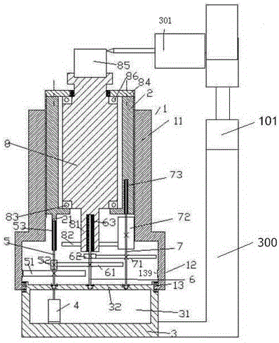
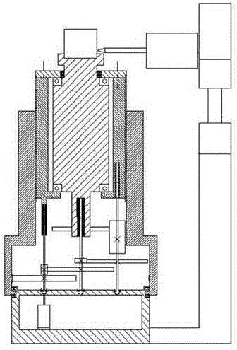
[0012] Attached below Figure 1-2 , the present invention will be described in detail.

[0013] A helical gear processing equipment that can be raised and lowered, used for processing the blank 85, it includes: a base 3, a column 300, a milling processing head 301, a rotatable internal threaded part 1, an external threaded part 2 and a cylindrical The workpiece carrier 8, wherein the base 3 is fixedly connected to the lower end of the column 300, the upper end of the column 300 is equipped with a lifting device 101, and the upper end of the lifting device 101 is equipped with a milling processing head 301, and the milling processing head 301 can be rotated by the milling cutter. The blank 85 is cut, and the rotatable internal threaded part 1 includes an upper cylindrical part 11 and a lower chamber part 12, and the lower chamber part 12 is connected to the base 3 in a circumferentially rotatable and axially fixed way through a bearing device 13 , the externally threaded membe...


PUM


Abstract

Spiral gear machining equipment capable of ascending and descending is used when a blank (85) is machined. The spiral gear machining equipment comprises a base (3), a stand column (300), a milling head (301), a rotary inner threaded part (1), an outer threaded part (2) and a cylindrical workpiece bearing part (8), wherein the base (3) is fixedly connected with the lower end of the stand column (300), a lifting device (101) is installed at the upper end of the stand column (300), a milling head (301) is installed at the upper end of the lifting device (101) and can mill the blank (85) through rotation of a milling cutter, the rotary inner threaded part (1) comprises an upper barrel part (11) and a lower cavity part (12), the lower cavity part (12) is rotationally connected with the base (3) in the peripheral direction and fixedly connected with the base (3) in the axial direction trough a bearing device (13), and the outer threaded part (2) is cylindrical.

Description

technical field [0001] The invention relates to the field of gear processing, in particular to the processing of helical gears. Background technique [0002] The helical gear has the advantages of good meshing, stable transmission and low noise. Moreover, the overlapping ratio is large, which reduces the load of each pair of gears and improves the bearing capacity of the gears. And the minimum number of teeth without undercutting is small. Because the meshing surface is small-large-small, the meshing is smooth, the impact is small, and the noise is low; therefore, it has a large load-carrying capacity, which can improve the life and stability of the gear; and it is small in size. The helical gear transmission is composed of two helical gears meshing together. The purpose is to transmit the movement between two phases of space. However, the manufacture of helical gears is cumbersome, and it is difficult to guarantee the shape and position accuracy of the processed tooth g...

Claims


Application Information

Patent Timeline
Patent Type & Authority Patents(China)
IPC IPC(8): B23F9/00B23Q5/48B23Q5/28
Inventor 刘佳艺陈壮
Owner 刘佳艺
Learn More