Automatic folding device for bag corner and folding method and auxiliary opening and closing part of automatic folding device

A driving device and corner technology, applied in packaging, transportation and packaging, paper/cardboard containers, etc., can solve problems such as inability to guarantee high efficiency and quality stability, decline in efficiency and quality, fatigue of human eyes, etc., to achieve design Reasonable layout, simple structure, and the effect of reducing labor intensity

Active Publication Date: 2015-03-25
张启辉
7 Cites 12 Cited by

AI-Extracted Technical Summary

Problems solved by technology

[0003] However, it is a very skillful task to bend the corners of the aforementioned cement packaging bags out of the aforementioned built-in valve ports. Now the common corner bending methods in bag manufacturing factories are all done by hand, using the cooperation of manual movements and human eye observations. The production efficiency is low, and the production efficiency...

Abstract

The invention discloses an automatic folding device for a bag corner and a folding method and an auxiliary opening and closing part of the automatic folding device. The device comprises a bag opening pressing mechanism, the auxiliary opening and closing part, a first mechanical arm, an opening and closing control mechanism and a pressing block. The auxiliary opening and closing part is used for turning a bag opening. The first mechanical arm is used for driving the opening and closing part to automatically move or driving a bag and the bag opening pressing mechanism to move automatically. The opening and closing control mechanism is used for controlling the opening and closing part to be automatically opened or closed. The pressing block is used for pressing the bag corner after the bag is opened. The opening and closing part is used as an auxiliary tool for corner folding of the bag opening. Corner folding can be rapidly achieved through opening and closing of the opening and closing part, the folding position and angle are adjustable and controllable, efficiency is high, and quality is stable. Particularly, the auxiliary opening and closing part is used, and then in cooperation with the bag opening pressing mechanism, the mechanical arm, the opening and closing control mechanism and the pressing block, the corner folding can be automatically achieved; a traditional manual operation mode is replaced, in this way, the efficiency is greatly improved, meanwhile, labor is saved, and the labor intensity of workers is relieved.

Application Domain

Container making machinery

Technology Topic

ManipulatorEngineering +2

Image

  • Automatic folding device for bag corner and folding method and auxiliary opening and closing part of automatic folding device
  • Automatic folding device for bag corner and folding method and auxiliary opening and closing part of automatic folding device
  • Automatic folding device for bag corner and folding method and auxiliary opening and closing part of automatic folding device

Examples

  • Experimental program(1)

Example Embodiment

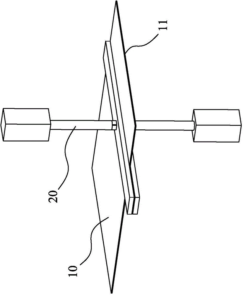
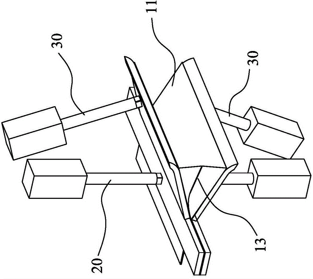
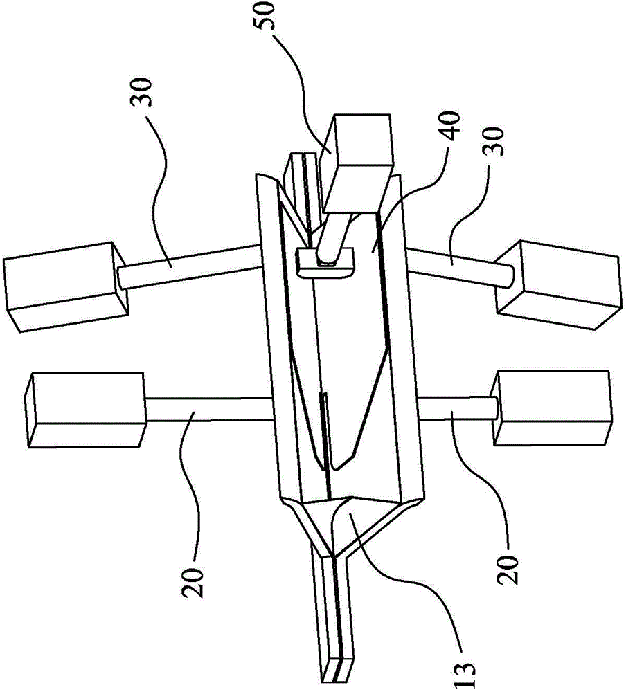
[0048] Please refer to Figure 1 to Figure 12 As shown, it shows the specific structure of the preferred embodiment of the present invention, including a bag body corner automatic folding device, including a bag body 10, a bag pressing mechanism 20, a pre-opening bag opening mechanism 30, and auxiliary opening and closing Piece 40, first manipulator 50, opening and closing control mechanism 60, pressing block 70 and second manipulator 80. The automatic corner turning device of the bag body in this embodiment is used to realize the automatic corner turning operation of the cement bag body 10.
[0049] Among them, such as figure 1 As shown, the bag-pressing mechanism 20 is used to press a proper position inside the bag mouth of the bag body 10, usually the position where the built-in valve mouth is located. The bag pressing mechanism 20 may be an air cylinder device or a hydraulic cylinder device or the like arranged above or below the bag body 10. The air cylinder device drives an elongated pressing plate to be pressed against the bag body 10.
[0050] Such as figure 2 As shown, the pre-opening bag opening mechanism 30 is used to open the bag opening 11 before the opening and closing member 40 enters the bag opening 11, so as to insert the opening and closing member 40 smoothly and accurately. The pre-opening bag opening mechanism 30 can be a vacuum adsorption type structure, or a hook type structure, etc., which can open one side of the bag separately, or can be provided on the upper and lower sides of the bag at the same time to open the bag at the same time. On both sides.
[0051] Combine image 3 with Picture 12 As shown, the auxiliary opening and closing member 40 is used to open the bag opening 11. The opening and closing member 40 includes two thin plates 41, one end of the two thin plates 41 is reversibly connected to each other, and the other end of the two thin plates 41 is free to open and close. end. At least one side of the connecting part 42 is provided with a relief groove 43, which can be used to avoid the inner flaps 13 existing on both sides of the bag. At least one side of the free ends of the two thin plates 41 is provided with The inclined surface 44 is used to fold the outer edge of the bag opening 11 inward. The angle of the inclined surface 44 is preferably between 30 and 60 degrees.
[0052] Combine Picture 9 , Picture 11 with Picture 12 As shown, the first manipulator 50 is used to drive the aforementioned opening and closing member 40 to move automatically, that is, to drive the opening and closing member 40 into and out of the bag opening 11, and to drive the opening and closing member 40 to move left and right in the bag.
[0053] A more specific example is that the first manipulator 50 includes a base 51, an X-axis drive device (not shown in the figure), an X-axis guide rail 53, an X-axis sliding seat 54, and a Y-axis drive device (not shown in the figure). Out), the Y-axis guide rail 55 and the Y-axis sliding seat 56, the X-axis guide rail 53 is arranged on the base 51, the Y-axis guide rail 55 is arranged on the X-axis sliding seat 54, and the aforementioned opening and closing member 40 is installed on the Y-axis sliding seat 56 The connection 42 of the opening and closing member 40 is installed and connected with the aforementioned Y-axis sliding seat 56; the X-axis sliding seat 54 is driven by the X-axis driving device to move back and forth along the X-axis guide rail 53, and the Y-axis driving device drives the Y-axis sliding seat 56 The Y-axis guide 55 moves left and right.
[0054] Combine Picture 11 with Picture 12 As shown, the opening and closing control mechanism 60 is used to control the aforementioned opening and closing member 40 to automatically open and close. The opening and closing control mechanism 60 is mounted on the aforementioned Y-axis sliding seat 56. The opening and closing control mechanism 60 includes a pawl 61, a pawl base 62 and a driving element (not shown in the figure). One end of the pawl 61 is connected to the pawl On the seat 62, the other end of the pawl 61 is connected to the free ends of the two thin plates 41, and the driving element drives the pawl seat 62 to move, thereby controlling the pawl to act on the two thin plates 41 and drive the two thin plates 41 to open and close.
[0055] Combine Figure 6 to Figure 10 As shown, the pressure block 70 is used to press the opened corner 13 of the bag body. It can use a second manipulator 80 to drive the pressure block 70 to move automatically, so as to compress the corner of the bag body at an appropriate time, and when appropriate The pressing block 70 is drawn out, and the way to withdraw the pressing block may be a linear movement type or a rotating type.
[0056] Next, the working principle, use method, or working process of this embodiment are described in detail as follows:
[0057] Such as figure 1 As shown, first, the bag opening mechanism 20 is used to press an appropriate position on the inner side of the bag opening 11.
[0058] Such as figure 2 As shown, the pre-opening bag opening mechanism 30 is used to pre-open the bag opening 11 to a smaller angle, so that the auxiliary opening and closing member 40 can be inserted.
[0059] Such as image 3 As shown, the auxiliary opening and closing member 40 in the closed state is then inserted into the bag opening 11, and the inner flap 13 of the bag body should be avoided during the insertion.
[0060] Such as Figure 4 As shown, the opening and closing member 40 is moved to the left, so that the recessed groove 43 on the opening and closing member 40 is clamped on the inner flap 13 of the bag body, so that the two thin plates 41 of the opening and closing member are respectively located on the bag body Both sides of the inner flap 13 are included.
[0061] Such as Figure 5 As shown, the opening and closing member 40 is then opened, so that the aforementioned inner flap 13 is pulled apart and straightened.
[0062] Such as Image 6 As shown, the pressing block 70 is used to press the middle of the straightened inner flap 13.
[0063] Such as Figure 7 As shown, the aforementioned opening and closing member 40 is folded and closed again, at this time, the corner of the aforementioned bag opening 11 is cornered to form a built-in valve opening 12.
[0064] Such as Figure 8 As shown, next, the first manipulator 50 drives the opening and closing member 40 to move back to the right to escape the inner flap 13 of the bag body.
[0065] Such as Picture 9 As shown, the first manipulator 50 controls the opening and closing member 40 to withdraw the bag mouth 11 as a whole.
[0066] Such as Picture 10 As shown, it is also necessary to use the second manipulator 80 to move the pressing block 70 to the left and extract it outward.
[0067] Finally, the bag opening 11 is sewn and sealed to shape the built-in valve opening 12 in the bag body.
[0068] It should be particularly noted that the first manipulator structure in the foregoing embodiment is not limited to the structure shown in the drawings, and the first manipulator is not limited to only driving the auxiliary opening and closing member to move, and it can also drive the bag body and the foregoing The bag opening mechanism moves together, and the function of inserting the opening and closing member into the bag opening can also be realized. The bag body in the foregoing embodiment is not limited to the bag body with inner folds. The automatic corner folding device of the present invention can also be applied to the bag body without inner folds. The notch can be eliminated; and it can also be applied to the structure of the bag opening with an extension piece, which is used to be folded into the bag body to form an elongated built-in valve port, which can more effectively prevent the cement dust from splashing out . Moreover, the automatic corner folding device of the present invention is not limited to cement bags, and can also be applied to various bag bodies that require corner folding.
[0069] In summary, the key point of the design of the present invention is that it uses an opening and closing piece as an auxiliary tool for corner folding of the bag mouth. The opening and closing of the opening and closing piece can achieve rapid corner folding, and the position and angle of the folding corner can be adjusted and controlled, and the efficiency is High and stable quality. In particular, the use of the auxiliary opening and closing part together with the bag pressing mechanism, manipulator, opening and closing control mechanism and pressing block can realize the automatic operation of corner folding, replacing the traditional manual operation method, making the entire processing action and processing steps simple. The efficiency is rapidly improved, while saving personnel and reducing the labor intensity of the staff.
[0070] The above are only the preferred embodiments of the present invention and do not limit the technical scope of the present invention. Therefore, any minor modifications, equivalent changes and modifications made to the above embodiments based on the technical essence of the present invention are still valid. It belongs to the scope of the technical solution of the present invention.

PUM

no PUM

Description & Claims & Application Information

We can also present the details of the Description, Claims and Application information to help users get a comprehensive understanding of the technical details of the patent, such as background art, summary of invention, brief description of drawings, description of embodiments, and other original content. On the other hand, users can also determine the specific scope of protection of the technology through the list of claims; as well as understand the changes in the life cycle of the technology with the presentation of the patent timeline. Login to view more.

Similar technology patents

Control circuit and method for a buck-boost power converter

ActiveUS20110074373A1improve efficiencyminimize output ripple
Owner:RICHTEK TECH

Classification and recommendation of technical efficacy words

  • Improve efficiency
Why Eureka
Try Eureka