A cooling system for a passenger car

A heat dissipation system and passenger car technology, applied in the field of passenger car heat dissipation system, can solve the problems of unsatisfactory heat dissipation, large fan distribution limitation, large energy consumption, etc., and achieve the effects of reasonable layout, easy implementation, and improved heat dissipation efficiency

Active Publication Date: 2017-01-11
ZHEJIANG BELORD DRIVE TECH
View PDF8 Cites 0 Cited by
  • Summary
  • Abstract
  • Description
  • Claims
  • Application Information

AI Technical Summary

Problems solved by technology

[0002] The fan of the vehicle in the prior art is generally connected by the output shaft of the engine and the input shaft of the fan to realize the operation of the fan. This kind of fan operation mode makes the distribution of the fan on the vehicle more restrictive and can The power consumption is also large, and the heat dissipation is not ideal

Method used


Image

  • A cooling system for a passenger car
  • A cooling system for a passenger car
  • A cooling system for a passenger car

Examples


Embodiment

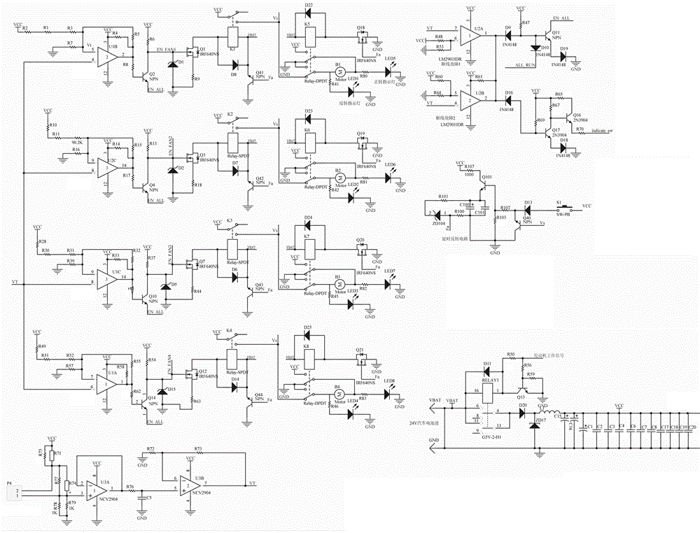
[0041] Embodiment: a kind of passenger car cooling system, such as Figure 1-7 As shown, it includes a water tank 101, an intercooler 102, and a fan 7. It is characterized in that the water tank 101 is located at the rear end side of the passenger car; the intercooler 102 and the water tank 101 are side by side along the length direction of the passenger car Setting; the fan 7 includes a first fan 71 configured for the water tank 101 to provide heat dissipation for the water tank 101, and a first fan 71 configured for the intercooler 102 to provide heat dissipation for the intercooler 102 Two fans 72; and each of the first fans 71 and each of the second fans 72 has an independent driving device.

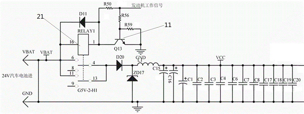
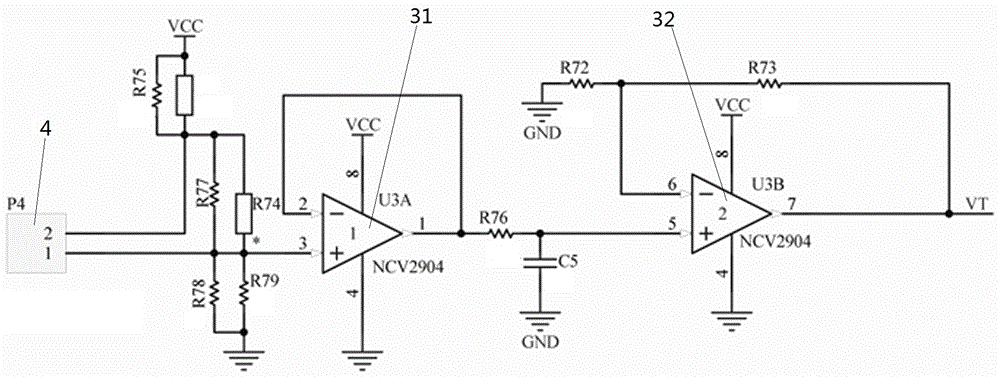
[0042] This embodiment also includes a fan intelligent control device, which includes a power supply device, a sensor device, a control device electrically connected to the sensor device, and an operating device electrically connected to the control device.

[0043] The power supply...


PUM


Abstract

The invention relates to cooling systems of vehicles, in particular to a passenger car cooling system. According to the technical scheme, the passenger car cooling system comprises a water tank, an intercooler and draught fans, wherein the water tank is located on the side edge of the rear end of a passenger car; the intercooler and the water tank are arranged side by side in the length direction of the passenger car; the draught fans comprise the first draught fans and the second draught fans, the first draught fans are arranged for the water tank and used for cooling the water tank, and the second draught fans are arranged for the intercooler and used for cooling the intercooler; in addition, all the first draught fans and all the second draught fans are provided with independent drive devices. The passenger car cooling system is beneficial to reasonable layout and capable of effectively improving cooling efficiency.

Description

technical field [0001] The invention relates to a cooling system of a vehicle, in particular to a cooling system of a passenger car. Background technique [0002] The fan of the vehicle in the prior art is generally connected by the output shaft of the engine and the input shaft of the fan to realize the operation of the fan. This kind of fan operation mode makes the distribution of the fan on the vehicle more restrictive and can The power consumption is also large, and the heat dissipation is not ideal. Contents of the invention [0003] The purpose of the present invention is to provide a passenger car heat dissipation system, which is beneficial to rational layout and effectively improves heat dissipation efficiency. [0004] The above-mentioned technical purpose of the present invention is achieved through the following technical solutions: a passenger car heat dissipation system, including a water tank, an intercooler, and a fan, and the water tank is located at the ...

Claims


Application Information

Patent Timeline
Patent Type & Authority Patents(China)
IPC IPC(8): B60K11/06B60K11/02F04D25/08F04D27/00
Inventor 吴泽滨陈浩沈董董姚荣根
Owner ZHEJIANG BELORD DRIVE TECH
Why Eureka
Try Eureka