
Night vision navigation integration system and control method

An integrated system and control method technology, applied in closed-circuit television systems, optical observation devices, signal devices, etc., can solve problems such as lack of active braking function, large difference between imaging sense and human eyes, unfavorable driving safety, etc.

Active Publication Date: 2015-03-25
CHONGQING CHANGAN AUTOMOBILE CO LTD
View PDF8 Cites 31 Cited by
  • Summary
  • Abstract
  • Description
  • Claims
  • Application Information

AI Technical Summary

Problems solved by technology

[0003] At present, except for a few high-end models, the passive night vision system mainly displays night vision video images through the car DVD, but there are cases where it works with the DVD navigation function at the same time, and does not have the active braking function
In addition, although the night vision system can detect pedestrians in advance, its imaging sense is quite different from that of the human eye, making it difficult to directly view
In addition, when the vehicle speed is high, although the direction of pedestrians can be clearly seen by zooming in on the image (for example, the BMW night vision system provides 1.5 times the image magnification when the vehicle speed is higher than a certain speed), but in the process of driving, the zoomed-in image will cause the image to be blurred. There is a difference between the sense of distance and the real situation, which is not conducive to driving safety

Method used


Image

  • Night vision navigation integration system and control method
  • Night vision navigation integration system and control method

Examples


Embodiment Construction

[0045] The present invention will be further described below in conjunction with accompanying drawing:

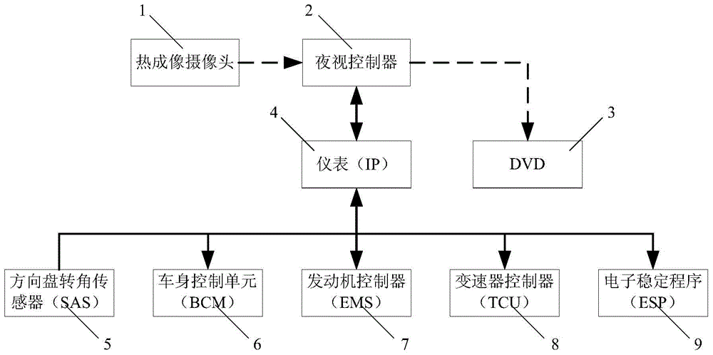
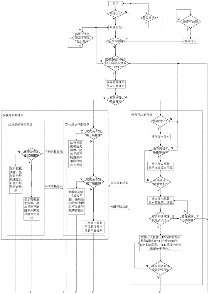
[0046] like figure 1 and figure 2 The night vision navigation integrated system shown includes thermal imaging camera 1, night vision controller 2, instrument (IP) 4, DVD3, steering wheel angle sensor (SAS) 5, body control unit (BCM) 6, engine controller (EMS ) 7, transmission controller (TCU) 8 and electronic stability program (ESP) 9. In this embodiment, the thermal imaging camera 1 is a thermal imaging camera. The thermal imaging camera 1 is connected with the night vision controller 2, the night vision controller 2 is respectively connected with the instrument 4, DVD3, and the instrument 4 is respectively connected with the steering wheel angle sensor 5, the body control unit 6, the engine controller 7, the transmission controller 8 and the electronic The stabilization program 9, that is, the night vision controller 2 communicates with the steering wheel angle senso...


PUM


Abstract

The invention discloses a night vision navigation integration system and a control method. The night vision navigation integration system comprises a thermal imaging camera, a night vision controller, an instrument, a DVD, a steering wheel angle sensor, a vehicle body control unit, an engine controller, a transmission controller and an electronic stability program. The thermal imaging camera collects road condition images. The night vision controller analyzes a video signal, identifies a pedestrian in the video signal, judges the relative distance between a vehicle and the pedestrian and relative speeds of the vehicle and the pedestrian according to a steering wheel angle signal, a vehicle speed signal and the installation position of the thermal imaging camera, predicts movement tracks of the vehicle and the pedestrian, judges the collision risk degree of the vehicle and the pedestrian, and sends out warning instructions and / or braking request instructions of different grades according to the collision risk degree. The instrument sends out warning information. The engine controller restrains throttle percentage responses generated by an engine on an accelerator pedal. The electronic stability program controls active pressurization of a pressure cylinder. The night vision navigation integration system and the control method can improve running safety.

Description

technical field [0001] The invention belongs to automobile active safety technology, and in particular relates to a night vision navigation integrated system and a control method. Background technique [0002] Driving at night, due to insufficient light, it is easy to find traffic accidents. According to statistics, more than half of the traffic fatal accidents occur at night, so a night vision system with pedestrian recognition has appeared. Through this system, pedestrians can be detected in advance compared with high beams, and the driver can be warned by images or sounds, so that it has sufficient Time to take collision avoidance measures. [0003] At present, except for a few high-end models, the passive night vision system mainly displays night vision video images through the car DVD, but there are cases where it works with the DVD navigation function at the same time, and does not have the active braking function. In addition, although the night vision system can de...

Claims


Application Information

Patent Timeline
IPC IPC(8): B60R1/00H04N7/18B60Q9/00B60W30/08B60W30/09
CPCB60Q9/008B60R1/00B60R2300/10B60W30/08B60W30/09H04N7/18
Inventor 任传兵黎予生张强孔周维万凯林
Owner CHONGQING CHANGAN AUTOMOBILE CO LTD
Learn More