carrier catapult

A technology for catapults and aircraft carriers, which is applied in the direction of launching/dragging transmissions, etc., which can solve the problems of high manufacturing difficulty, low ejection speed or ejection cycle, and high maintenance costs, and achieve low manufacturing difficulty, low manufacturing cost, and long manufacturing cycle. short effect

Active Publication Date: 2017-02-15
宋朋东
View PDF6 Cites 0 Cited by
  • Summary
  • Abstract
  • Description
  • Claims
  • Application Information

AI Technical Summary

Problems solved by technology

[0009] The purpose of the present invention is to solve the deficiencies of existing catapult technical solutions, such as old technical solutions, excessive total weight, low ejection speed or ejection cycle, high manufacturing difficulty, high manufacturing cost, high maintenance cost, and excessive occupation of the internal space of the aircraft carrier. And provide a new technical solution: use several high-power diesel engines, rationally use the role of worm and other machinery, force the carrier-based aircraft to reach the take-off speed within a distance of 100 meters

Method used


Image

  • carrier catapult
  • carrier catapult
  • carrier catapult

Examples


Embodiment Construction

[0028] The present invention will be further described below in conjunction with accompanying drawing and specific embodiment:

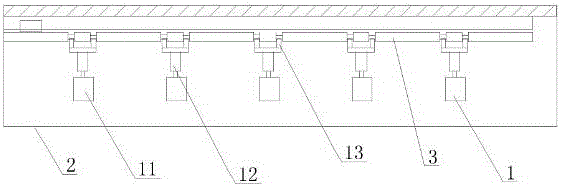
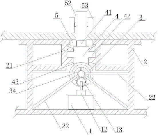
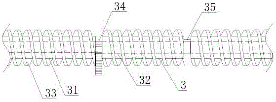
[0029] Such as figure 1 , figure 2 As shown, a carrier catapult includes a power system 1, a catapult fixed frame 2, a worm 3, a stressed slider 4, and a slide plate 5; the catapult fixed frame 2 is fixed below the deck of an aircraft carrier, and the catapult An opening is provided on the deck of the aircraft carrier above the fixed frame 2, which is commonly referred to as a slideway; one end of the slide plate 5 is located above the deck of the aircraft carrier, and the other end is socketed with the stressed slide block 4; the slide of the stressed slide block 4 The wing 42 is embedded in the slide rail 21 of the catapult fixed frame 2 and can slide in the slide rail; all the force-bearing teeth 43 below the force-bearing slider 4 are engaged with a part of the worm 3; the power system 1 drives the worm 3 turn.

[0030] Such as figure 2 , ...


PUM


Abstract

The invention provides a carrying aircraft catapult. The carrying aircraft catapult comprises a power system, a catapult fixing frame, a worm, a stress sliding block and a sliding plate; the catapult fixing frame is fixed below a deck of an aircraft carrier, an opening, namely a sliding way, is formed in the portion, above the catapult fixing frame, of the deck of the aircraft carrier, one end of the sliding plate is located above the deck of the aircraft carrier, the other end of the sliding plate is arranged on a protruding head of the stress sliding block in a sleeving mode, the stress sliding block is embedded into a sliding rail of the catapult fixing frame and can slide in the sliding rail, the worm is meshed with the lower portion of the stress sliding block, and the power system drives the worm to rotate. The carrying aircraft catapult has the advantages that the size is small, constant accelerated speed catapulting can be achieved, rapid catapulting under the condition that the aircraft carrier is not against the wind can be achieved, the catapulting frequency per minute is greatly increased, fresh water is not consumed, electromagnetic radiation is avoided, the catapult manufacturing cost and the manufacturing difficulty are greatly reduced, the manufacturing period is short, the maintaining cost is low, and the energy dissipation is low.

Description

[0001] 【Technical field】 [0002] The invention relates to a catapult, in particular to an aircraft carrier aircraft catapult. [0003] 【Background technique】 [0004] The aircraft carrier catapult currently in use in the world is the steam catapult of the United States; the latest electromagnetic catapult in the United States has also been tested for several years, and it is close to success; there are no reports of the successful manufacture of steam catapults and electromagnetic catapults in China, let alone ejection Test reports. [0005] After inquiry, there are more than a dozen catapult patents in related fields in China, but among the several invention patents that have obtained patent rights, none of the main technical indicators that are expected to be realized can surpass the latest model of steam catapults in use in the United States and the United States. The latest electromagnetic catapult. [0006] More than 60 years ago, when the production and processing tech...

Claims


Application Information

Patent Timeline
Patent Type & Authority Patents(China)
IPC IPC(8): B64F1/06
Inventor 宋朋东
Owner 宋朋东
Why Eureka
Try Eureka