Bi-order grid spiral wave ion propulsion device

Inactive Publication Date: 2015-03-25
DALIAN UNIV OF TECH
View PDF6 Cites 20 Cited by
  • Summary
  • Abstract
  • Description
  • Claims
  • Application Information

AI Technical Summary

Problems solved by technology

[0005] The present invention aims at the problem of insufficient specific impulse and thrust performance of the propulsion device proposed above, and researches and designs a double-stage grid helical wave ion propulsion device

Method used


Image

  • Bi-order grid spiral wave ion propulsion device
  • Bi-order grid spiral wave ion propulsion device
  • Bi-order grid spiral wave ion propulsion device

Examples


Embodiment Construction

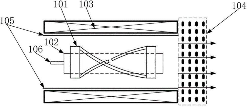
[0015] Such as figure 1 As shown, a double-stage grid helicon wave ion propulsion device includes a discharge chamber 102, a helicon wave excitation antenna 101, a metal sleeve 105, an electromagnetic coil 103 and a double-stage grid system 104, and is sleeved outside the discharge chamber 102 , the helical wave excitation antenna 101 and the discharge chamber 102 are both arranged inside the metal sleeve 105, coaxially arranged with the metal sleeve 105, the electromagnetic coil 103 is sleeved outside the metal sleeve 105, and the electromagnetic coil 103 mainly plays the role of The metal sleeve 105 functions as a magnetic field, and the metal sleeve 105 acts as a shield while shielding the helical wave excitation antenna 101 from radiating energy to the external space, so that all the power generated by radio frequency is confined in the discharge chamber 102 . The top of the discharge chamber is provided with a working medium gas inlet 106, and the working medium gas suppl...


PUM


Abstract

The invention discloses a bi-order grid spiral wave ion propulsion device which comprises a discharge chamber, a spiral wave excitation antenna, a metal sleeve, an electromagnetic coil and a bi-order grid system. The spiral wave excitation antenna is connected with a radio-frequency power source and is arranged outside the discharge chamber in a sleeving mode, the spiral wave excitation antenna and the discharge chamber are both arranged inside the metal sleeve, and the metal sleeve is sleeved with the electromagnetic coil. The bi-order grid system is arranged at the tail end of the discharge chamber. The bi-order grid system comprises a screen grid, an extraction grid, an accelerating grid and a decelerating grid which are sequentially arranged away from the discharge chamber from near to far, and the screen grid, the extraction grid, the accelerating grid and the decelerating grid are all provided with grid holes. According to the bi-order grid spiral wave ion propulsion device, the mode that a spiral wave plasma source and the bi-order grid system are combined is adopted, the propulsion device can work under high power, and thus the reliable performance of high specific impulse and high propulsion capability can be achieved.

Description

technical field [0001] The invention relates to the technical field of spacecraft engines and space propulsion, in particular to a double-stage grid helical wave ion propulsion device. Background technique [0002] Currently, space propulsion is used for spacecraft during the spaceflight phase, and its function is to provide power for missions such as spacecraft attitude control, north-south position keeping, orbital maneuvering, and deorbiting. Space propulsion technology can generally be divided into chemical propulsion and electric propulsion, as well as some other propulsion technologies (such as nuclear energy propulsion, solar sail propulsion technology). At present, electric propulsion technology has gradually become the preferred solution for small thrust propulsion devices in space due to its advantages in high specific impulse, while the missions of long-lived satellites and distant star exploration vehicles are characterized by long flight time and long-term pertu...

Claims


Application Information

Patent Timeline
Patent Type & Authority Applications(China)
IPC IPC(8): F03H1/00
CPCF03H1/00
Inventor 夏广庆徐宗琦郝剑昆薛伟华王鹏邹存祚吴秋云周念东
Owner DALIAN UNIV OF TECH
Why Eureka
Try Eureka