
Hydraulic cylinder

A technology for hydraulic cylinders and cylinders, applied in the field of hydraulic cylinders, can solve problems such as easily damaged cylinders, inability to cool cylinders, poor hydraulic effects, etc., and achieve the effects of improving hydraulic effects, improving sealing performance, and prolonging service life

Inactive Publication Date: 2015-03-25
SHANGHAI YAOHUA TECH DEV
View PDF1 Cites 2 Cited by
  • Summary
  • Abstract
  • Description
  • Claims
  • Application Information

AI Technical Summary

Problems solved by technology

[0002] With the development of social production and the rapid development of the machinery industry, a large number of hydraulic cylinders are produced and used. With the extensive development of the hydraulic industry, the role of hydraulic cylinders in operations cannot be ignored. The application number is CN 200810191084.6, which discloses a Hydraulic cylinder, which is located inside a hydraulic section for operating a vehicle's clutches or brakes, the function of which is improved by allowing the piston rod to implement only small swing angles, thereby reducing the contact points of moving components wear and at the same time increase the service life of the hydraulic cylinder, in that the piston unit, which is axially movable inside the housing, is configured in the front region facing the pressure chamber as a bearing point relative to the housing and the rotation of the piston unit The point is in the area of ​​the primary sealing device embedded in the front area of ​​the piston unit, but the hydraulic cylinder cannot cool the cylinder body when performing hydraulic operations, and the high temperature is easy to damage the cylinder body, the piston sealing performance is better, and the hydraulic effect Difference

Method used


Image

  • Hydraulic cylinder

Examples


Embodiment Construction

[0012] In order to make the technical means, creative features, goals and effects achieved by the present invention easy to understand, the present invention will be further described below in conjunction with specific illustrations.

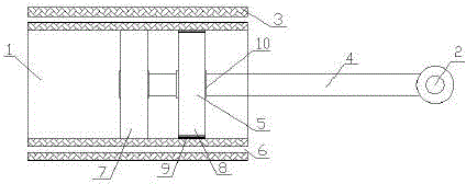
[0013] Such as figure 1 As shown, a hydraulic cylinder according to the present invention includes a cylinder body 1 and a piston 2, the cylinder body 1 is provided with an outer heat insulating device 3, the piston 2 includes a plug rod 4 and a plug plate 5, and the outer The heat insulation device 3 is provided with a liquid injection through hole 6, the plug plate 5 includes a front plate 7 and a rear plate 8, and the rear plate 8 is connected with a seal 9, and the cooling liquid is injected through the liquid injection through hole during hydraulic operation. It flows through to cool the cylinder body, prevent high temperature from damaging the cylinder body, and prolong the service life of the hydraulic cylinder. The plug plate is set as t...


PUM


Abstract

The invention discloses a hydraulic cylinder. The hydraulic cylinder comprises a cylinder body and a piston, wherein an outer heat insulating device is arranged on the cylinder body; the piston comprises a piston rod and a piston plate; a liquid injecting through hole is formed in the outer heat insulating device; the piston plate comprises a front plate and a back plate; and the back plate is connected with a sealing piece. When the hydraulic operation is performed, cooling liquid flows through the liquid injecting through hole for cooling the cylinder body to prevent high temperature from damaging the cylinder body, so that the service life of the hydraulic cylinder is prolonged; the piston plate is set as the front and back plates to enable the piston to have a better sealing performance so as to improve the hydraulic effect; and the hydraulic cylinder is convenient and practical, and is suitable for promotion and application.

Description

technical field [0001] The invention relates to the field of hydraulic equipment, in particular to a hydraulic cylinder. Background technique [0002] With the development of social production and the rapid development of the machinery industry, a large number of hydraulic cylinders are produced and used. With the extensive development of the hydraulic industry, the role of hydraulic cylinders in operations cannot be ignored. The application number is CN 200810191084.6, which discloses a Hydraulic cylinder, which is located inside a hydraulic section for operating a vehicle's clutches or brakes, the function of which is improved by allowing the piston rod to implement only small swing angles, thereby reducing the contact points of moving components wear and at the same time increase the service life of the hydraulic cylinder, in that the piston unit, which is axially movable inside the housing, is configured in the front region facing the pressure chamber as a bearing point ...

Claims


Application Information

Patent Timeline
Patent Type & Authority Applications(China)
IPC IPC(8): F15B15/16F16J10/02F16J1/12F16J9/28
CPCF15B15/1485F15B15/1447F15B15/1452
Inventor 程齐姚昕昕汪梅花
Owner SHANGHAI YAOHUA TECH DEV
Learn More