Oil cylinder with mechanical locking function and hydraulic system

A mechanical locking and functional technology, applied in the field of hydraulic pressure, can solve the problems of the oil cylinder lifting position not falling, the oil cylinder lifting position falling, and zero leakage can not be achieved, so as to avoid leakage, avoid hydraulic oil compression, and keep it from falling Effect

Inactive Publication Date: 2015-03-25
ZOOMLION ENVIRONMENTAL IND CO LTD
View PDF6 Cites 16 Cited by
  • Summary
  • Abstract
  • Description
  • Claims
  • Application Information

AI Technical Summary

Problems solved by technology

[0005] However, using the hydraulic lock 70 to keep the lifting position of the oil cylinder from falling has the following disadvantages. The first: the sealing method of the existing hydraulic lock 70 is a mechanical seal, which cannot achieve zero leakage. In the working state, as time goes by, hydraulic oil will flow out from the first oil port 21, causing the lifting position of the o

Method used


Image

  • Oil cylinder with mechanical locking function and hydraulic system
  • Oil cylinder with mechanical locking function and hydraulic system
  • Oil cylinder with mechanical locking function and hydraulic system

Examples


Example Embodiment

[0023] In order to further illustrate the technical means and effects of the present invention to achieve the intended purpose of the invention, the present invention will be described in detail below with reference to the drawings and preferred embodiments.

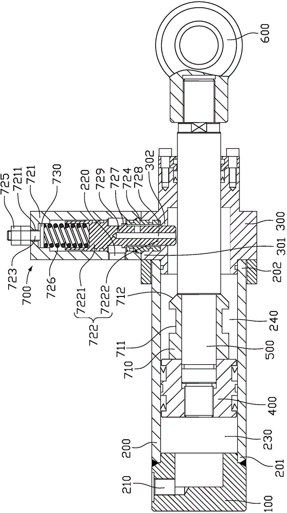
[0024] figure 2 It is a structural schematic diagram of an oil cylinder with a mechanical locking function in an embodiment of the present invention, such as figure 2 As shown, the cylinder includes a cylinder head 100, a cylinder barrel 200, a cylinder head 300, a piston 400, a piston rod 500, a front ear ring 600, and a piston rod locking device 700. The piston 400 is installed at one end of the piston rod 500 extending into the cylinder 200. The cylinder 200 has a first end 201 and a second end 202 opposite to each other. The cylinder 200 is formed between the piston 400 and the first end 201 of the cylinder 200 A rodless cavity 230, a rod cavity 240 is formed in the cylinder 200 between the piston 400 and the second en...


PUM


Abstract

An oil cylinder with the mechanical locking function comprises a cylinder barrel, a piston and a piston rod, wherein the piston is installed at the end, extending into the cylinder barrel, of the piston rod; the cylinder barrel is provided with a first end and a second end opposite to the first end; a rodless cavity is formed in the position, between the piston and the first end of the cylinder barrel, in the cylinder barrel; a rod cavity is formed in the position, between the piston and the second end of the cylinder barrel, in the cylinder barrel; a piston rod locking device is installed on the cylinder barrel in the radial direction of the cylinder barrel; the piston rod locking device comprises a sleeve, a locking pin and an elastic part; the sleeve is installed on the cylinder barrel in the radial direction of the cylinder barrel; the locking pin is installed in the sleeve and can slide along the sleeve; the first end of the locking pin penetrates through the cylinder barrel via the sleeve and extends into the rod cavity; the elastic part is installed in the sleeve and applies axial compression force to the second end of the locking pin; a locking groove is formed in the piston rod; when the piston rod extends out to enable the locking pin to align with the locking groove, the first end of the locking pin extends into the locking groove, so that the piston rod is locked at the extending-out position. The invention further provides a hydraulic system comprising the oil cylinder.

Description

technical field [0001] The invention relates to the field of hydraulic technology, in particular to an oil cylinder with a mechanical locking function and a hydraulic system with the oil cylinder. Background technique [0002] In the prior art, in order to keep the lifting position of the oil cylinder from falling, a hydraulic lock is generally added to the hydraulic system, such as figure 1 As shown, the oil cylinder includes a cylinder head 10 , a cylinder barrel 20 , a piston 30 , a piston rod 40 , a guide sleeve 50 and a cylinder cover 60 . One end of the cylinder 20 is provided with a first oil port 21 communicated with the rodless chamber, and the other end of the cylinder 20 is provided with a second oil port 22 communicated with the rod chamber, and the piston 30 is fixed on the The piston rod 40 moves in the cylinder barrel 20 under the push of oil pressure, the cylinder head 60 is set at the other end of the cylinder barrel 20 away from the cylinder head 10, and t...

Claims


Application Information

Patent Timeline
IPC IPC(8): F15B15/26F15B15/20
CPCF15B15/262F15B15/20
Inventor 张良军李利刘伯祥
Owner ZOOMLION ENVIRONMENTAL IND CO LTD
Why Eureka
Try Eureka