
Multi-channel high-pressure gas mechanical reversing mechanism

A technology of high-pressure gas and mechanical reversing, applied in the direction of mechanical equipment, multi-way valves, valve housing structures, etc., can solve the problems of difficult maintenance, reduced work efficiency, expensive maintenance costs, etc., to avoid failures, simple structure, easy to use The effect of easy maintenance

Inactive Publication Date: 2015-03-25
吴笑伟 +4
View PDF5 Cites 6 Cited by
  • Summary
  • Abstract
  • Description
  • Claims
  • Application Information

AI Technical Summary

Problems solved by technology

[0002] At present, in the field of mechanical engineering, the multi-way reversing mechanism of high-pressure gas mostly uses valves for reversing. Its structure is complex and bulky, and the use of many valves will lead to low reliability and difficult maintenance.
In addition, due to the complex structure, problems are prone to occur. After problems occur, not only expensive maintenance costs are required, but also work efficiency is reduced.

Method used


Image

  • Multi-channel high-pressure gas mechanical reversing mechanism
  • Multi-channel high-pressure gas mechanical reversing mechanism
  • Multi-channel high-pressure gas mechanical reversing mechanism

Examples


Embodiment Construction

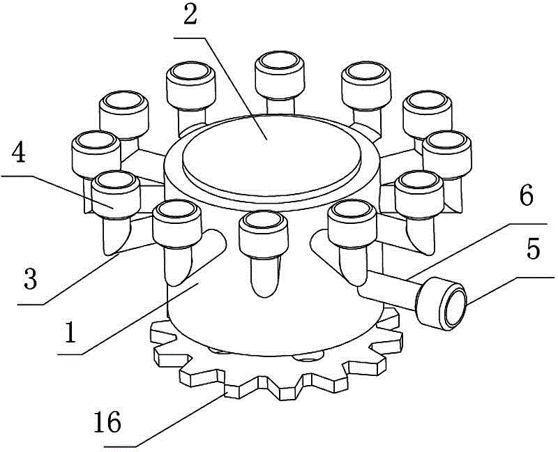
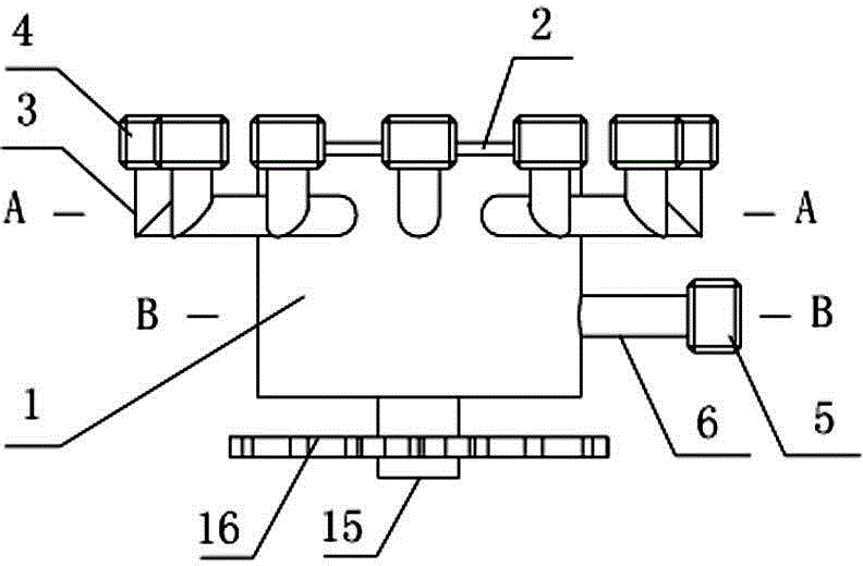
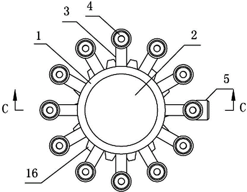
[0015] Such as Figure 1-6 As shown, the multi-channel high-pressure gas mechanical reversing mechanism of the present invention includes a valve casing 1 with a cylindrical cavity, and a cylindrical valve core 2 inserted in the cylindrical cavity of the valve casing 1; The upper part of the outer peripheral surface of the valve housing 1 is evenly distributed along the circumferential direction with twelve air outlets, and each of the air outlets is fixedly connected with an air outlet pipe 3 with an L-shaped structure, and the air outlet of the L-shaped air outlet pipe 3 is set upwards. And a pipe joint 4 is installed; the lower part of the outer peripheral surface of the valve housing 1 is provided with an air inlet, and the air inlet is fixedly connected with an air inlet pipe 6 with a pipe joint 5; the outer peripheral surface of the cylindrical valve core 2 is from top to bottom. There are three annular grooves 7, 8, 9 separated at the lower part, and sealing rings are r...


PUM


Abstract

The invention discloses a multi-channel high-pressure gas mechanical reversing mechanism. The multi-channel high-pressure gas mechanical reversing mechanism comprises a valve casing with a cylindrical through cavity, and a cylinder valve element plugged in the cylindrical through cavity of the valve casing in an interval mode, wherein multiple air outlets are evenly formed in the upper portion of the valve casing in the circumferential direction; each air outlet is fixedly connected with an air outlet pipe; an air inlet is formed in the lower portion of the peripheral surface of the valve casing; three annular grooves are formed in the peripheral surface of the cylinder valve element at intervals from top to bottom; an air outlet channel is formed at the position, between the first annular groove and the second annular groove, of the peripheral surface of the cylinder valve element and located at the height position of the air outlets; the air outlet channel extends to the axis position of the cylinder valve element; an air guide annular groove is formed in the position, between the second annular groove and the third annular groove, of the peripheral surface of the cylinder valve element and located at the height position of the air inlet; air inlet channels are formed in the bottom of the air guide annular groove in the radial direction; an air guide channel communicated with the air outlet channel is upwards formed in the junction of the air inlet channels. The multi-channel high-pressure gas mechanical reversing mechanism has the advantage that the purely mechanical structure is adopted, so that the fault problems that a traditional solenoid valve needs to be supplied with power and is switched uninterruptedly are solved.

Description

technical field [0001] The invention relates to a high-pressure gas reversing mechanism, in particular to a multi-channel high-pressure gas mechanical reversing mechanism. Background technique [0002] At present, in the field of mechanical engineering, the multi-way reversing mechanism of high-pressure gas mostly uses valves for reversing. Its structure is complex and bulky, and the use of many valves will lead to low reliability and difficult maintenance. In addition, due to the complex structure, it is very prone to problems, which not only require expensive maintenance costs, but also reduce work efficiency. Contents of the invention [0003] The purpose of the present invention is to provide a multi-channel high-pressure gas mechanical reversing mechanism. [0004] To achieve the above object, the present invention takes the following technical solutions: [0005] The multi-channel high-pressure gas mechanical reversing mechanism of the present invention includes a ...

Claims


Application Information

Patent Timeline
Patent Type & Authority Applications(China)
IPC IPC(8): F16K11/085F16K31/53F16K27/06
CPCF16K11/085F16K27/06F16K31/53
Inventor 吴笑伟张俊冷传广魏彦召张秀如
Owner 吴笑伟
Learn More