Real-time monitoring method of electric actuator of large valve

An electric actuator, real-time monitoring technology, applied to engine components, valve operation/release devices, valve details, etc., can solve the problem of shortening the service life of valves, aggravating the wear of valve core and valve inner cavity, and protecting the process of inability to travel, etc. problems, to avoid major accidents

Active Publication Date: 2017-01-04
TIANJIN AIKETE MEASUREMENT CONTROL TECH
View PDF8 Cites 0 Cited by
  • Summary
  • Abstract
  • Description
  • Claims
  • Application Information

AI Technical Summary

Problems solved by technology

[0006] The problem with the above method is: only calibrate the point of 100% rated torque, and establish the corresponding relationship between 100% rated torque and analog-to-digital conversion value, and the analog-to-digital conversion value corresponding to the rest of the percentage torque is obtained by calculation
It is impossible to truly realize the protection of the electric actuator and the valve during the full stroke operation process, let alone the early warning of the full stroke torque change and the preventive protection of the equipment during the long-term operation of the electric actuator and valve
That is to say, during use, if the middle part of the valve is opened, there is a small foreign matter in the contact part between the valve core and the inner cavity of the valve body. Since the valve opens the middle part, the required torque is very small. The existence of such a small foreign matter usually does not As a result, the torque required to open the valve exceeds the set torque protection value, so the existing monitoring equipment will not alarm, but small foreign objects in the contact between the valve core and the inner cavity of the valve body will aggravate the tension between the valve core and the inner cavity of the valve body. Wear and tear, greatly shorten the service life of the valve

Method used


Image

  • Real-time monitoring method of electric actuator of large valve
  • Real-time monitoring method of electric actuator of large valve
  • Real-time monitoring method of electric actuator of large valve

Examples


Embodiment Construction

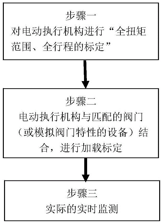
[0028] Specific embodiments of the invention will be described in detail below in conjunction with the accompanying drawings.

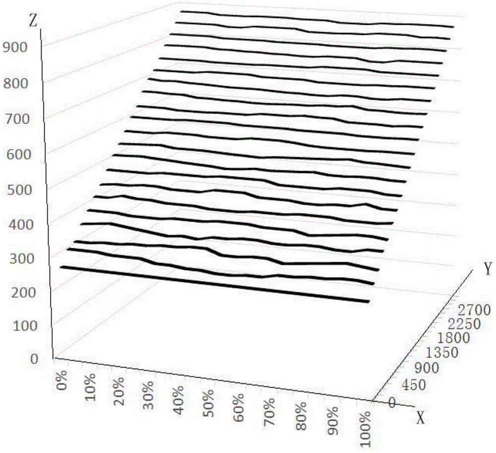
[0029] figure 1 It is a schematic flow diagram of the main steps of the present invention, such as figure 1 As shown, in step 1, firstly carry out "full torque range and full stroke calibration" on the electric actuator to obtain the following figure 2 The data table of "actual output torque value & stroke value --- analog-to-digital conversion value" shown is a three-dimensional data table.

[0030]

[0031] In this step, while performing range calibration on the analog-to-digital conversion value corresponding to the actual output torque value, the identification of the corresponding stroke position is added. Therefore, each actual stroke position and actual torque corresponds to an analog-to-digital conversion value, forming a Three-dimensional data table, the specific method is given as an example: starting from 0% of the rated torque, the ele...


PUM


Abstract

The invention provides a real-time monitoring method of an electric actuator of a large valve. The real-time monitoring method comprises the following steps: firstly, calibrating a full torque range and a full stroke of the electric actuator to obtain a corresponding relation of a stroke position value, a real-time output torque and an analog-digital conversion value; then, calibrating the loading of the electric actuator and the value to obtain a data table of stroke vales and analog-digital conversion values of corresponding matched values; in practical operation, obtaining a real-time analog-digital conversion value and a real-time stroke position value to extract the actual output torque value of the corresponding electric actuator, and meanwhile, comparing the real-time analog-digital conversion value with the analog-digital conversion value corresponding to the corresponding stroke value in the data table of stroke vales and analog-digital conversion values, in order to judge the operation state of the valve in real time, alarm and analyze the failure of the electric actuator and carry out preventive maintenance to avoid the incidence of major accidents.

Description

technical field [0001] The invention relates to the field of torque monitoring of electric actuators of large valves, in particular a method for real-time monitoring of torque. Background technique [0002] At present, more and more factories adopt automatic control, and manual operation is replaced by mechanical or automatic equipment. Therefore, the use of electric actuators can play an interface role between the control system and the mechanical movement of valves, and electric actuators are required to enhance work safety. performance and environmental protection performance. In some dangerous occasions, the automatic actuator device can reduce the injury of personnel. Similarly, real-time monitoring of the operating status of electric actuators is becoming more and more important. [0003] The main purpose of monitoring the working state of the electric actuator is to protect the valve and the electric actuator. The traditional monitoring method is: firstly, the outpu...

Claims


Application Information

Patent Timeline
Patent Type & Authority Patents(China)
IPC IPC(8): F16K37/00F16K31/04
CPCF16K31/04F16K37/0025
Inventor 曹式录张丽芳王婷婷高洪庆高亮亮
Owner TIANJIN AIKETE MEASUREMENT CONTROL TECH
Why Eureka
Try Eureka