
Thin oil returning structure of conical heads of uncoiling machine and coiling machine

A coiler and uncoiler technology, applied in the direction of mechanical equipment, engine components, engine lubrication, etc., can solve problems such as leakage, reduce cone bearing friction and take away frictional heat, cone oil leakage, etc.

Inactive Publication Date: 2015-03-25
镇江市宏业科技有限公司
View PDF7 Cites 2 Cited by
  • Summary
  • Abstract
  • Description
  • Claims
  • Application Information

AI Technical Summary

Problems solved by technology

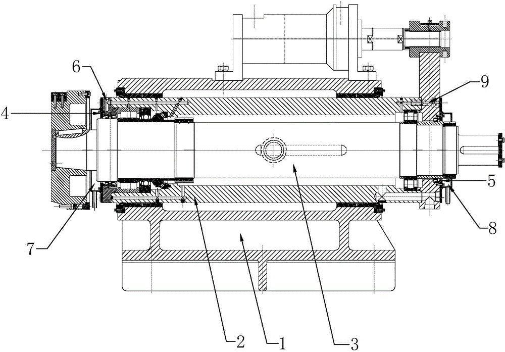
[0003] During the use of the aluminum foil mill, due to the needs of the production process, the uncoiling cone will use a thin oil lubrication system to lubricate the bearings in the cone, thereby reducing the friction in the cone bearing and taking away the frictional heat, thereby prolonging the life of the bearing service life; however, since the oil intake of thin oil is controlled by the thin oil pump system, and the return of oil is through potential energy return; poor oil return will lead to oil leakage from the cone head, polluting the coil surface and the site environment; at the same time, set The vent plug of the air hole on the top of the conical head seat, it is easy for thin oil to leak from the vent hole during the working process

Method used


Image

  • Thin oil returning structure of conical heads of uncoiling machine and coiling machine
  • Thin oil returning structure of conical heads of uncoiling machine and coiling machine

Examples


Embodiment Construction

[0012] The thin oil return structure of the cone head of the uncoiler and the coiler of the present invention will be further described in detail below in conjunction with the accompanying drawings and specific embodiments.

[0013] As shown in the figure, the thin oil return structure of the conical head of the uncoiler and coiler of the present invention includes a conical head seat 1 and a sliding sleeve 2 installed in the conical head seat 1. A rotating shaft 3 is installed in the sliding sleeve 2, and the rotating shaft Two bearings are installed between 3 and sliding sleeve 2, one bearing is installed on the front end of rotating shaft 3 and sliding sleeve 2, and the other bearing is installed on the rear end of rotating shaft 3 and sliding sleeve 2, forming between rotating shaft 3 and sliding sleeve 2 The closed lubricating chamber also includes a vent hole 9 communicating with the lubricating chamber. The vent hole 9 includes a radial hole vertically arranged in the sl...


PUM


Abstract

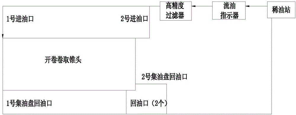
The invention discloses a thin oil returning structure of conical heads of an uncoiling machine and a coiling machine. The thin oil returning structure comprises a conical head base and a slide sleeve, wherein a rotary shaft is arranged in the slide sleeve; a bearing arranged between the rotary shaft and the slide sleeve is respectively arranged at each of the front and rear ends of each of the rotary shaft and the slide sleeve; a sealed lubricating cavity and an air hole are formed between the rotary shaft and the slide sleeve; a front end cover and a rear end cover are respectively arranged at the front and the rear ends of the slide sleeve; the left and right ends of the lubricating cavity are sealed and capped by virtue of the front end cover and the rear end cover; a first oil inlet is formed in the front end cover, and a second oil inlet is formed in the rear end cover; a first oil collecting plate is connected to the front end cover; an oil returning opening of the first oil collecting plate is connected to a thin oil station; a second oil collecting plate is connected to the rear end cover; an oil returning opening of the second oil collecting plate is also connected to the thin oil station. Through the adoption of the thin oil returning structure disclosed by the invention, the lubricating oil is intensively collected in the oil collecting plate while leaking from the sealing ring; the lubricating oil is collected to avoid polluting the spot environment, the oil returning amount is greased, and the oil returning efficiency is greatly improved.

Description

[0001] technical field [0002] The invention relates to a cone head device on a double-cone head clamping device, in particular to a thin oil return structure of the cone head of an uncoiler and a coiler, belonging to the technical field of aluminum processing equipment. Background technique [0003] During the use of the aluminum foil mill, due to the needs of the production process, the uncoiling cone will use a thin oil lubrication system to lubricate the bearings in the cone, thereby reducing the friction in the cone bearing and taking away the frictional heat, thereby prolonging the life of the bearing service life; however, since the oil intake of thin oil is controlled by the thin oil pump system, and the return of oil is through potential energy return; poor oil return will lead to oil leakage from the cone head, polluting the coil surface and the site environment; at the same time, set The air vent plug in the air hole on the top of the cone seat is easy to leak th...

Claims


Application Information

Patent Timeline
IPC IPC(8): F16N31/00B21C47/00
Inventor 张媛媛
Owner 镇江市宏业科技有限公司
Learn More