LED floor tile lamp

A technology of LED lamp beads and floor tile lamps, which is used in outdoor lighting, lighting applications, lighting and heating equipment, etc., can solve the problems of high voltage, inconvenient installation, complex structure, etc., and achieve strong variability, safe use and installation and maintenance, simple structure

Inactive Publication Date: 2015-03-25
赵立平
View PDF0 Cites 3 Cited by
  • Summary
  • Abstract
  • Description
  • Claims
  • Application Information

AI Technical Summary

Problems solved by technology

This kind of LED floor tile light can only be controlled by an external controller, and cannot emit corresponding light with the movement of performers on the stage
[0003] Now there are also some LED floor tile lights with induction structure, incl

Method used


Image

  • LED floor tile lamp
  • LED floor tile lamp

Examples


Example Embodiment

[0013] The technical solutions in the embodiments of the present invention will be clearly and completely described below in conjunction with the drawings in the embodiments of the present invention.

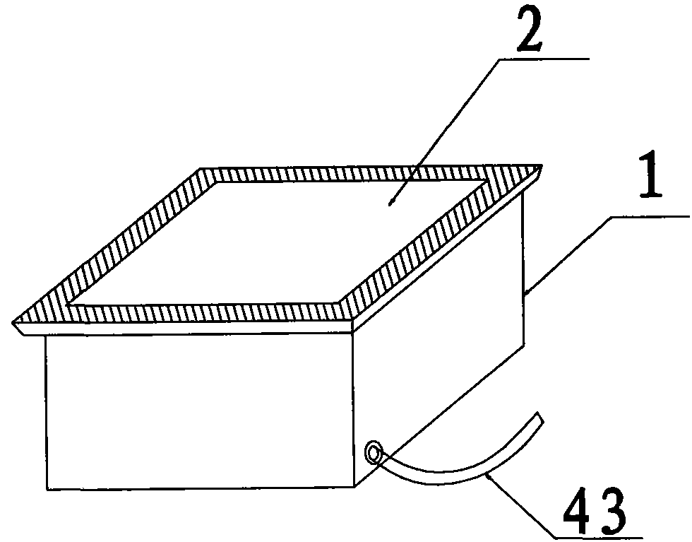
[0014] The invention provides an LED floor tile lamp, such as figure 1 As shown in the structural diagram, the LED floor tile lamp has a simple structure, is fashionable and novel, can recognize pressure and emit light, uses low-voltage safety electricity, and is safe to use and maintain.

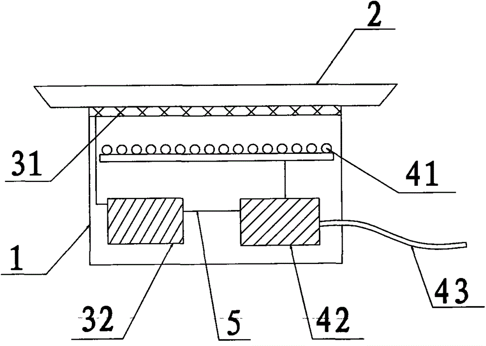
[0015] Such as figure 2 As shown, the LED floor tile lamp includes a housing 1, a tempered glass 2 on the top of the housing 1, and a pressure sensing device 3 and a light emitting device 4 located inside the housing; the pressure sensing device 3 and the light emitting device 4 are electrically connected.

[0016] The pressure sensing device 3 includes a pressure sensor 31 located under the tempered glass 2 and a pressure controller 32 connected to the pressure sensor 31. The pressure sensor 31 ca...


PUM


Abstract

The invention discloses an LED floor tile lamp. The LED floor tile lamp comprises a shell, a piece of tempered glass which is located on the top of the shell, and a pressure sensing device and a light emitting device which are located in the shell. The pressure sensing device is electrically connected with the light emitting device. The LED floor tile lamp is simple in structure, fashionable and novel; low-voltage safe electricity is used, and therefore the LED floor tile lamp is quite safe and convenient to install and maintain.

Description

technical field [0001] The invention relates to a decorative lamp, in particular to an LED floor tile lamp. Background technique [0002] At present, on the stage of many evening parties, catwalks and other occasions, most of them create different lighting effects and stage atmosphere by laying luminous LED floor tile lights. The general LED floor tile lamp is mainly composed of a housing, a light source arranged in the housing and a light-transmitting body buckled on the housing. When working, it emits light of different colors through a preset mode. This kind of LED floor tile light can only be controlled by an external controller, and cannot emit corresponding light with the movement of performers on the stage. [0003] Now there are also some LED floor tile lights with induction structure, including piezoelectric induction sheet, conductor, main circuit board and other structures. The structure is complex, installation is inconvenient, and the voltage used is high, whic...

Claims


Application Information

Patent Timeline
IPC IPC(8): F21S8/02F21V23/04F21Y101/02F21W131/105F21W131/406
CPCF21S8/022F21V23/0442F21W2131/105F21W2131/406F21Y2101/00
Inventor 赵立平
Owner 赵立平
Why Eureka
Try Eureka