
A visual inspection machine

An inspection machine and video technology, which is applied in the field of video inspection machines, can solve the problems of large equipment size, unsuitable adjustment, and difficult fixing of products, and achieve the effect of good verification results, high test consistency, and convenient loading and unloading

Active Publication Date: 2017-08-01
常熟晶晟汽车零部件有限公司
View PDF4 Cites 0 Cited by
  • Summary
  • Abstract
  • Description
  • Claims
  • Application Information

AI Technical Summary

Problems solved by technology

[0002] (1) Most of the existing technologies use multiple CCD decomposition tests. For example, the test pin position degree φ0.4 will be decomposed into X and Y directions for separate testing, which will increase equipment investment and relatively large equipment volume; 2) Existing technologies generally use conversion benchmarks for testing. For example, if some test elements are not on the same plane or interfere with shooting, fixed fixtures will be used to convert test benchmarks, which will also increase equipment investment and should not be adjusted; (3) The product itself It is difficult to fix. If multi-station separate positioning test is used, it is difficult to meet the MSA requirements and the repeatability is poor.

Method used


Image

  • A visual inspection machine
  • A visual inspection machine
  • A visual inspection machine

Examples


Embodiment Construction

[0014] The preferred embodiments of the present invention will be described below in conjunction with the accompanying drawings. It should be understood that the preferred embodiments described here are only used to illustrate and explain the present invention, and are not intended to limit the present invention.

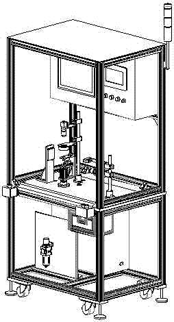
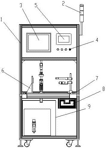
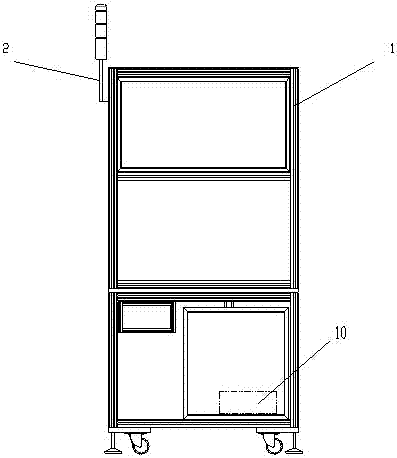
[0015] Such as Figure 1-4 As shown, a video inspection machine includes an aluminum profile frame 1, a button box 7, a defective product box 8, an electrical control box 9, a DMV controller 10, and a fixture assembly 6. Color indicator light 2, display 3, key switch 4 with indicator button, touch screen 5 are arranged on the inner upper part of aluminum profile frame 1; fixture assembly 6 is arranged on the inner middle part of frame 1; fixture assembly 6 includes servo motor 61, bearing Seat 62, clamping cylinder 63, linear lighting body 64, digital camera 65, ring lighting body 66, backlight lighting body 67, shell positioning cylinder 68, clamping cylinder 63 is...


PUM


Abstract

The invention discloses a video inspection machine. The video inspection machine comprises a rack, a button box, a disqualified product box, an electric control box, a DMV controller and a clamp assembly, a single-color indicator lamp is arranged on the outer side of the rack, a displayer, a key switch and a touch screen are arranged on the upper portion on the inner side of the rack, and the clamp assembly is arranged in the middle of the inner side of the rack. The clamp assembly comprises a servo motor, a bearing pedestal, a clamping air cylinder, digital cameras, lighting bodies and a shell positioning air cylinder, the clamping air cylinder and the servo motor are connected and fixed to the two sides of the bearing pedestal of a bottom plate, the upper portion of the clamping air cylinder is connected with the shell positioning air cylinder on a middle frame of the annular lighting body, and the backlight lighting body, the linear lighting body and the annular lighting body are installed on the portion, around the clamping air cylinder, of the bottom plate in a positioned mode; the button box is installed on the portion, on the rear side of the linear lighting body, of the bottom plate, the disqualified product box and the electric control box are installed on the lower side of the bottom plate, the DMV controller is connected with the displayer, the digital cameras, the touch screen and the lighting bodies, and all the components are connected with the electric control box.

Description

technical field [0001] The invention belongs to the field of auto parts, in particular to a video inspection machine. Background technique [0002] (1) Most of the existing technologies use multiple CCD decomposition tests. For example, the test pin position degree φ0.4 will be decomposed into X and Y directions for separate testing, which will increase equipment investment and relatively large equipment volume; 2) Existing technologies generally use conversion benchmarks for testing. For example, if some test elements are not on the same plane or interfere with shooting, fixed fixtures will be used to convert test benchmarks, which will also increase equipment investment and should not be adjusted; (3) The product itself It is difficult to fix. If the multi-station separate positioning test is used, it is difficult to meet the MSA requirements and the repeatability is poor. Contents of the invention [0003] The invention aims to overcome the defects of the prior art and...

Claims


Application Information

Patent Timeline
Patent Type & Authority Patents(China)
IPC IPC(8): G01B11/00
Inventor 汤旭炎诸建明潘忠林
Owner 常熟晶晟汽车零部件有限公司
Learn More