Hypersonic wind tunnel airflow stabilizing device

A technology with stable airflow and hypersonic speed, which is applied in the field of aerodynamics, can solve the problems of uneven heating of the wall surface of the casing, reducing the compressive strength of the casing, and limiting the heating temperature of the stable section, so as to reduce the risk of wind tunnel operation, Effects of shortened start-up time and low heat loss

Active Publication Date: 2015-03-25
CHINA ACAD OF AEROSPACE AERODYNAMICS
View PDF4 Cites 14 Cited by
  • Summary
  • Abstract
  • Description
  • Claims
  • Application Information

AI Technical Summary

Problems solved by technology

The method adopted is to wrap the electric heating tape outside the shell of the stable section, however, the heating temperature of the stable section must be limited in this way
Considering the pressure resistance requirements of the shell, the heating temperature is generally limited to below 200°C to prevent uneven heating of the wall surface of the shell shell and local heating to reduce the compressive strength of the shell shell. Thicker, large heat absorption, slow temperature rise, large power consumption, resulting in waste
For wind tunnels with Ma greater than 7, there is a certain risk in applying this method. If the wind tunnel works under the condition of a higher Ma number, the working pressure of the main air flow is generally greater than 5.0MPa, and there is a risk in using shell wall heating. In actual engineering, generally do not use

Method used


Image

  • Hypersonic wind tunnel airflow stabilizing device
  • Hypersonic wind tunnel airflow stabilizing device
  • Hypersonic wind tunnel airflow stabilizing device

Examples


Embodiment Construction

[0027] The principles and features of the present invention will be described in detail below in conjunction with the accompanying drawings.

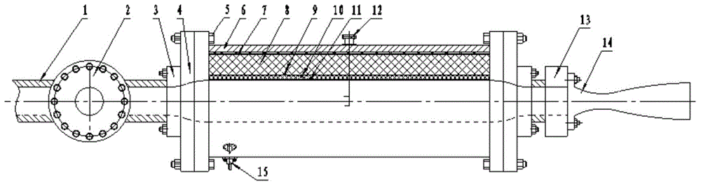
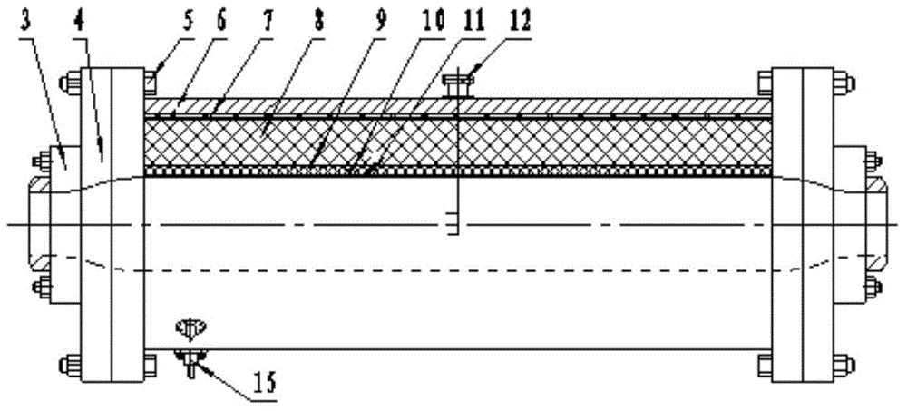
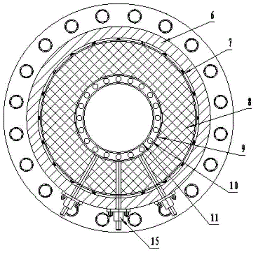
[0028] Such as figure 1 As shown in the system diagram of the airflow stabilization device, there are high-temperature and high-pressure pipelines 1 and high-temperature, high-pressure quick valve 2 in the front of the wind tunnel stabilization section, which are the air source input parts of the stabilization section, and the high-temperature and high-pressure airflow from the heater is passed through the control and input stable segment. The airflow decelerates, diffuses, and stabilizes in the stable section, and then passes through the contraction section to reach the outlet. The outlet of the stable section is connected to the locking mechanism 13, and is connected to the nozzle 14 through a hydraulic mechanism or a bolt fastener. There is a bent frame mounting seat 12 in the middle section of the shell cylinder 6, and the temperat...


PUM


Abstract

The invention provides a hypersonic wind tunnel airflow stabilizing device. The hypersonic wind tunnel airflow stabilizing device comprises a shell cylinder, a sliding cylinder, a supporting cylinder, a heating element and a heat storage cylinder. The two ends of the shell cylinder are each provided with a flange. The sliding cylinder, the supporting cylinder and the heat storage cylinder are sequentially arranged in the shell cylinder. A plurality of bosses are welded to the outer wall of the sliding cylinder and arranged in the shell cylinder in the manner of abutting against the inner surface of the shell cylinder. A heat insulation layer is fixed between the sliding cylinder and the supporting cylinder. The heating element is installed between the supporting cylinder and the heat storage cylinder. The heat storage cylinder is a cylinder with a smooth inner wall and is provided with a front expansion segment, a middle straight segment and a rear contraction segment, one end of the heat storage cylinder is welded to the flange at one end of the shell cylinder, and the other end of the heat storage cylinder is inserted in the flange at the other end of the shell cylinder. According to the hypersonic wind tunnel airflow stabilizing device, the starting time of a wind tunnel is shortened obviously, testing efficiency is improved, manufacturing is facilitated, and installation is convenient.

Description

technical field [0001] The invention relates to the field of aerodynamics, in particular to a conventional hypersonic wind tunnel equipment component and an airflow stabilizing section device with an electric heating function. Background technique [0002] When a conventional hypersonic wind tunnel is in operation, the air flow in the wind tunnel passes through pipes, valves, heaters and other equipment, causing large disturbances, turbulent flow, and uneven flow velocity; before the main airflow enters the nozzle, an airflow stabilization device is required to rectify it in order to achieve uniform flow velocity. There is no deflection in the airflow direction along the nozzle axis, and the airflow turbulence is low. In use, there are different stable section structures according to the difference in airflow temperature in the wind tunnel. [0003] Usually, the way for wind tunnels to rectify the normal temperature and low temperature airflow is to add perforated plates, h...

Claims


Application Information

Patent Timeline
Patent Type & Authority Applications(China)
IPC IPC(8): G01M9/04
Inventor 郭孝国王宏亮
Owner CHINA ACAD OF AEROSPACE AERODYNAMICS
Why Eureka
Try Eureka