
Cooling control method, device and system

A control method and technology of heat dissipation unit, which are applied in the fields of instruments, electrical digital data processing, digital data processing components, etc., and can solve the problems of fan power loss and slow temperature change of radiator.

Inactive Publication Date: 2015-03-25
LANGCHAO ELECTRONIC INFORMATION IND CO LTD
View PDF5 Cites 19 Cited by
  • Summary
  • Abstract
  • Description
  • Claims
  • Application Information

AI Technical Summary

Problems solved by technology

The heat sink has a certain heat capacity. When the power of the main components increases, the control unit must wait for the temperature of the heat sink to rise before the control unit can adjust the fan accordingly. The power of the main components such as the CPU and memory in the server changes rapidly. However, the temperature on the radiator changes slowly, causing the fan to run at high speed all the time, resulting in excessive power loss of the fan

Method used


Image

  • Cooling control method, device and system
  • Cooling control method, device and system
  • Cooling control method, device and system

Examples


Embodiment Construction

[0049] In order to make the purpose, technical solutions and advantages of the embodiments of the present invention clearer, the technical solutions in the embodiments of the present invention will be clearly and completely described below in conjunction with the drawings in the embodiments of the present invention. Obviously, the described embodiments It is a part of the embodiments of the present invention, but not all of them. Based on the embodiments of the present invention, all other embodiments obtained by those of ordinary skill in the art without creative work belong to the protection of the present invention. scope.

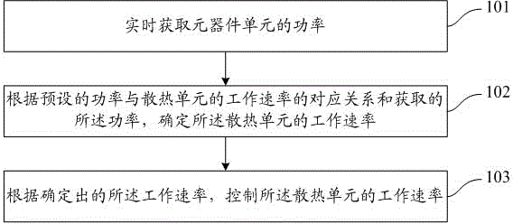
[0050] During the working process of the components, when the working power of the components is high, the heat emitted by the components is more, and when the working power of the components is small, the heat emitted by the components is less, in order to keep the temperature of the components at Within a certain range, the temperature of the componen...


PUM


Abstract

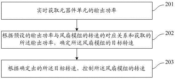
The invention provides a cooling control method, device and system. The method includes the steps of obtaining the power of an element unit in real time, determining the working speed of a cooling unit according to the correspondence between the preset power and the working speed of the cooling unit and according to the obtained power, and controlling the working speed of the cooling unit according to the determined working speed. By means of the cooling control method, device and system, the power loss of the cooling unit can be reduced.

Description

technical field [0001] The invention relates to the technical field of heat dissipation of components, in particular to a heat dissipation control method, device and system. Background technique [0002] The cooling architecture of the server has a very important impact on the server performance and power consumption level. Thermal architecture is also an important indicator to measure the level of server design. [0003] In the prior art, the heat dissipation system of the server collects the temperature around the target component through the temperature detection unit, and adjusts the fan speed according to the detected temperature. [0004] It can be seen from the above description that in the prior art, the fan speed is adjusted passively by accepting temperature changes. The heat sink has a certain heat capacity. When the power of the main components increases, the control unit must wait for the temperature of the heat sink to rise before the control unit can adjust ...

Claims


Application Information

Patent Timeline
Patent Type & Authority Applications(China)
IPC IPC(8): G06F1/20
CPCG06F1/20
Inventor 王武军
Owner LANGCHAO ELECTRONIC INFORMATION IND CO LTD
Learn More