Unlock instant, AI-driven research and patent intelligence for your innovation.
CNFET type double-edge pulse type JKL trigger
What is Al technical title?
Al technical title is built by PatSnap Al team. It summarizes the technical point description of the patent document.
A double edge, trigger technology, applied in the direction of pulse generation, pulse technology, generation of electrical pulses, etc., can solve problems such as limiting process development
Active Publication Date: 2016-11-09
NINGBO UNIV
View PDF5 Cites 6 Cited by
Summary
Abstract
Description
Claims
Application Information
AI Technical Summary
This helps you quickly interpret patents by identifying the three key elements:
Problems solved by technology
Method used
Benefits of technology
Problems solved by technology
[0002] With the development of Moore's law, integrated circuit technology has entered the deep submicron stage, and the small size effect of MOS tubes limits the further development of the technology
Method used
Image
Click on the blue label to locate the original text in one second.
Reading with bidirectional positioning of images and text.
Examples
Embodiment 1
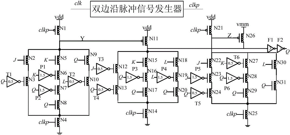
[0029] Embodiment one: if figure 1 As shown, a CNFET double-edge pulse JKL flip-flop includes a double-edge pulse signal generator, a first CNFET tube N1, a second CNFET tube N2, a third CNFET tube N3, a fourth CNFET tube N4, and a fifth CNFET tube. Tube N5, sixth CNFET tube N6, seventh CNFET tube N7, eighth CNFET tube N8, ninth CNFET tube N9, tenth CNFET tube N10, eleventh CNFET tube N11, twelfth CNFET tube N12, thirteenth CNFET tube CNFET tube N13, fourteenth CNFET tube N14, fifteenth CNFET tube N15, sixteenth CNFET tube N16, seventeenth CNFET tube N17, eighteenth CNFET tube N18, nineteenth CNFET tube N19, twenty CNFET tube Tube N20, twenty-first CNFET tube N21, twenty-second CNFET tube N22, twenty-third CNFET tube N23, twenty-fourth CNFET tube N24, twenty-fifth CNFET tube N25, twenty-sixth CNFET tube N26 , the twenty-seventh CNFET tube N27, the twenty-eighth CNFET tube N28, the twenty-ninth CNFET tube N29, the thirty-first CNFET tube N30, the thirty-first CNFET tube N31, s...
Embodiment 2
[0030] Embodiment two: if figure 1As shown, a CNFET double-edge pulse JKL flip-flop includes a double-edge pulse signal generator, a first CNFET tube N1, a second CNFET tube N2, a third CNFET tube N3, a fourth CNFET tube N4, and a fifth CNFET tube. Tube N5, sixth CNFET tube N6, seventh CNFET tube N7, eighth CNFET tube N8, ninth CNFET tube N9, tenth CNFET tube N10, eleventh CNFET tube N11, twelfth CNFET tube N12, thirteenth CNFET tube CNFET tube N13, fourteenth CNFET tube N14, fifteenth CNFET tube N15, sixteenth CNFET tube N16, seventeenth CNFET tube N17, eighteenth CNFET tube N18, nineteenth CNFET tube N19, twenty CNFET tube Tube N20, twenty-first CNFET tube N21, twenty-second CNFET tube N22, twenty-third CNFET tube N23, twenty-fourth CNFET tube N24, twenty-fifth CNFET tube N25, twenty-sixth CNFET tube N26 , the twenty-seventh CNFET tube N27, the twenty-eighth CNFET tube N28, the twenty-ninth CNFET tube N29, the thirty-first CNFET tube N30, the thirty-first CNFET tube N31, si...
PUM
Property
Measurement
Unit
Diameter
aaaaa
aaaaa
Diameter
aaaaa
aaaaa
Diameter
aaaaa
aaaaa
Abstract
The invention discloses a carbon nanotubefield effecttransistor (CNFET) type double-edge pulse type JKL trigger. The CNFET type double-edge pulse type JKL trigger comprises a double-edge pulse signal generator, thirty-first CNFET tubes, six NTI gate circuits with the same circuit structure, six PTI gate circuit with the same circuit structure, a first ternary phaseinverter and a second ternary phaseinverter, wherein the first ternary phaseinverter and the second ternary phase inverter have the same circuit structure. The CNFET type double-edge pulse type JKL trigger has the advantages: a clocksignal is generated by utilizing the double-edge pulse signal generator; by combining switching operation of a multi-value logic circuit and high-speed low-power features of CNFET, a purpose of reducing the power consumption is achieved when the working speed of the JKL trigger is improved; and based on experiment results, the JKL trigger provided by the invention has a correct logic function and remarkable characteristic of low power consumption.
Description
technical field [0001] The invention relates to a JKL trigger, in particular to a CNFET double edge pulse JKL trigger. Background technique [0002] With the development of Moore's law, the integrated circuit process has entered the deep submicron stage, and the small size effect of the MOS tube limits the further development of the process. Carbon NanotubeField EffectTransistor (CNFET, Carbon NanotubeField EffectTransistor), as a new type of device, has attracted widespread attention from designers due to its ballistic transmission characteristics, small leakage current and channel capacitance, which are beneficial to the design of high-performance and low-power integrated circuits, and has become a substitute One of the candidate materials for silicon-based. [0003] High-performance flip-flops are of great significance to high-speed and low-power sequential circuits. With the advantage of short settling time and single-latch structure, pulse flip-flops are receiving...
Claims
Application Information
Patent Timeline
Application Date:The date an application was filed.
Publication Date:The date a patent or application was officially published.
First Publication Date:The earliest publication date of a patent with the same application number.
Issue Date:Publication date of the patent grant document.
PCT Entry Date:The Entry date of PCT National Phase.
Estimated Expiry Date:The statutory expiry date of a patent right according to the Patent Law, and it is the longest term of protection that the patent right can achieve without the termination of the patent right due to other reasons(Term extension factor has been taken into account ).
Invalid Date:Actual expiry date is based on effective date or publication date of legal transaction data of invalid patent.

