
A gate drive circuit and display device thereof

A gate drive circuit and gate drive technology, applied to static indicators, instruments, etc., can solve the problems that the charge cannot be released immediately, there is no way to eliminate the residual image after shutdown, and the residual image can be eliminated, so as to achieve the effect of eliminating the residual image after shutdown

Active Publication Date: 2017-01-18
KUSN INFOVISION OPTOELECTRONICS
View PDF5 Cites 0 Cited by
  • Summary
  • Abstract
  • Description
  • Claims
  • Application Information

AI Technical Summary

Problems solved by technology

However, when the thin film transistor liquid crystal display is powered off, due to the charging relationship, after the display has displayed images for a long time, it will cause charge accumulation in the liquid crystal capacitor, and these charges cannot be released immediately after the power is turned off, so when the power is turned off part of the previous image will remain on the momentary screen
[0003] However, in the existing gate drive circuit, the gate drive signal of each stage is controlled by the external clock signal and the gate drive signal fed back from the front and rear stages, which leads to all the gates being from top to bottom, or from bottom to top Turning on sequentially, there is no way to realize that all the gates are opened at the same time at the same time, and the liquid crystal capacitors in the liquid crystal display cannot be discharged at the same time. circuit to eliminate shutdown afterimage

Method used


Image

  • A gate drive circuit and display device thereof
  • A gate drive circuit and display device thereof
  • A gate drive circuit and display device thereof

Examples


Embodiment Construction

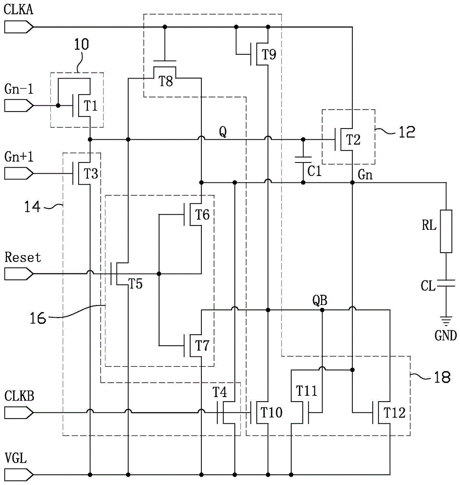
[0015] In order to make the above objects, features and advantages of the present invention more comprehensible, specific implementations of the present invention will be described in detail below in conjunction with the accompanying drawings.

[0016] Although the present invention uses the terms first, second, third, etc. to describe various elements, signals, ports, components or sections, these elements, signals, ports, components or sections are not limited by these terms. These terms are only used to distinguish one element, signal, port, component or section from another element, signal, port, component or section. In the present invention, an element, port, component or part is "connected" or "connected" to another element, port, component or part, which can be understood as a direct electrical connection, or can also be understood as an indirect electrical connection with an intermediate element. sexual connection. Unless otherwise defined, all terms (including techn...


PUM


Abstract

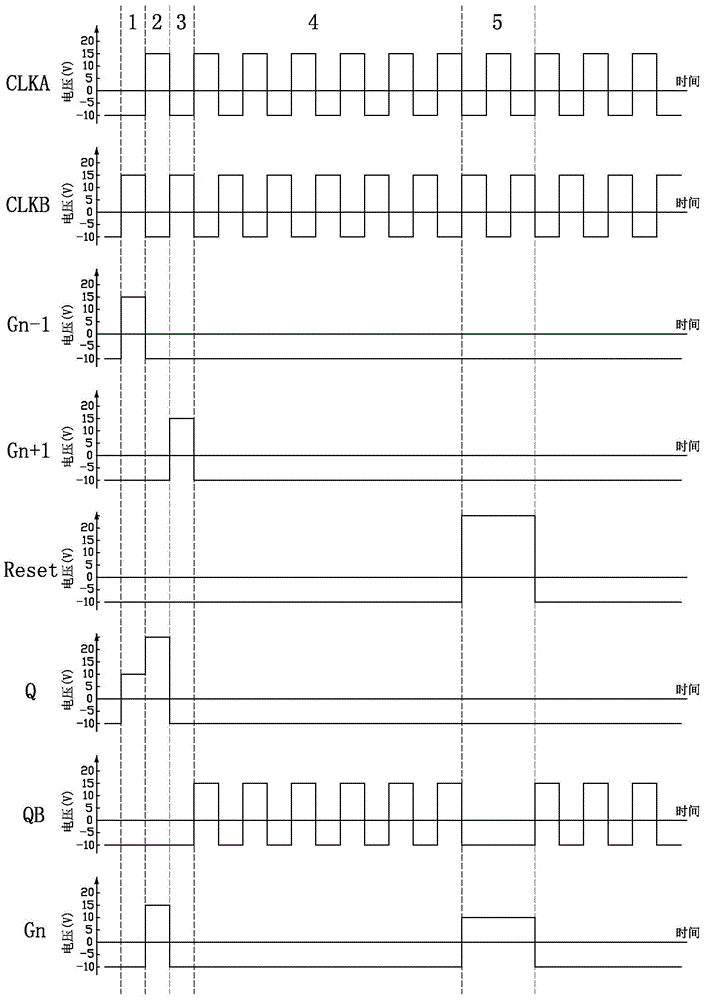
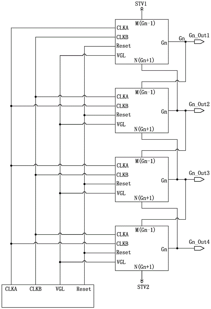
The invention discloses a grid electrode drive circuit. The grid electrode drive circuit comprises multiple stages of grid electrode drive units. Each stage of grid electrode drive unit comprises a pre-charging module, a pull-up module, a pull-down module and a resetting module. Each stage of grid electrode drive unit receives a first time sequence signal, a second time sequence signal, a next stage of grid electrode drive signal output to the next stage of grid electrode drive unit, a former stage of grid electrode drive signal output to the former stage of grid electrode drive unit and a resetting signal. The invention further provides a display device. The resetting modules in grid electrode drive circuit and the display device enable the grid electrode drive signal of each stage of grid electrode drive unit to output high potential simultaneously when the resetting signals are high potentials, thereby discharging accumulated electricity loads in a liquid crystal capacitor soon and further eliminating shut-down residual images.

Description

technical field [0001] The invention relates to the technical field of liquid crystal display, in particular to a gate drive circuit and a display device thereof. Background technique [0002] As liquid crystal displays are more and more applied to people's lives, various problems occurring in the process of liquid crystal display are also urgently needed to be solved by people. Among them, the afterimage after shutdown is a major problem in the process of LCD display. Liquid crystal displays generally store charges through storage capacitors and liquid crystal capacitors, so that the picture can be kept until the next new picture. However, when the thin film transistor liquid crystal display is powered off, due to the charging relationship, after the display has displayed images for a long time, it will cause charge accumulation in the liquid crystal capacitor, and these charges cannot be released immediately after the power is turned off, so when the power is turned off ...

Claims


Application Information

Patent Timeline
Patent Type & Authority Patents(China)
IPC IPC(8): G09G3/36
Inventor 李亚锋房耸邬金芳常琳
Owner KUSN INFOVISION OPTOELECTRONICS
Learn More