
A special sliding waste engine oil recovery device for automobiles

A recovery device and sliding technology, which is applied in the installation/connection of lubricant purification devices, lubricating parts, pressure lubricants, etc., can solve the problems of waste engine oil turbidity, pollution, high viscosity, etc., and reduce the time for cleaning the ground , reduce the workload, the effect of strong practicability

Active Publication Date: 2021-11-23
JIANGSU JIAOTONG COLLEGE
View PDF5 Cites 0 Cited by
  • Summary
  • Abstract
  • Description
  • Claims
  • Application Information

AI Technical Summary

Problems solved by technology

[0002] It is well known that after the engine oil in the automobile engine and gearbox is used for a period of time, impurities such as moisture, dust, other miscellaneous oils and metal powder produced by the wear and tear of the parts are mixed in the engine and gearbox, which leads to the occurrence of oil properties. change, the color turns black, and the viscosity increases, so the engine oil needs to be replaced regularly. The engine needs to discharge the used engine oil before changing the engine oil. The used engine oil removed from the car is a toxic substance and belongs to the solid hazardous waste marked by the state. , It is strictly forbidden to buy and sell waste engine oil at will. It should be handled by a qualified waste oil treatment company. When collecting waste engine oil, the waste engine oil in the waste engine oil barrel is generally taken out by dumping or pumping. It is easy to flow from the barrel to the ground and cause ground pollution. The staff still need to clean the ground, which increases the labor intensity of the staff. Waste oil treatment companies increase the time and cost of processing, increasing the burden on the company

Method used


Image

  • A special sliding waste engine oil recovery device for automobiles
  • A special sliding waste engine oil recovery device for automobiles
  • A special sliding waste engine oil recovery device for automobiles

Examples


Embodiment Construction

[0023] The present invention can be explained in detail through the following examples, and the purpose of disclosing the present invention is to protect all technical improvements within the scope of the present invention.

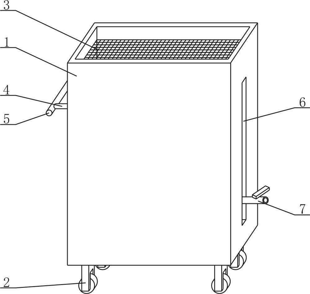
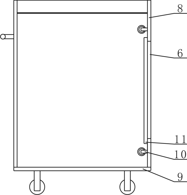
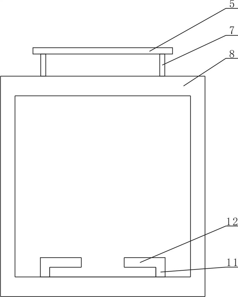
[0024] combined with Figure 1~5 A sliding type waste engine oil recovery device for automobiles, comprising a holding cylinder 1, wheels 2, connecting rod 4, grip rod 5, isolation net 3, fixing device, rotating device, fixing belt 15 and valve 7, on the holding cylinder 1 Be provided with wheel 2 and connecting rod 4, be provided with isolation net 3, rotating device and fixing device in the holding tube 1, be provided with handle bar 5 on the connecting rod 4, be provided with fixing band 15 on the fixing device, set on the fixing band 15 Valve 7 is arranged, and fixing device is made of connecting plate 11 and fixing plate 12, and connecting plate 11 is provided with fixing plate 12, and rotating device is made of fixing rod 10, rotating shaft 13 and s...


PUM


Abstract

A sliding type waste engine oil recovery device dedicated to automobiles, which relates to the technical field of automobile maintenance tools, including a holding cylinder, wheels, connecting rods, grip rods, isolation nets, fixing devices, rotating devices, fixing belts and valves. There are wheels and connecting rods. There are isolation nets, rotating devices and fixing devices in the storage tube. The connecting rods are equipped with grip rods. The fixing devices are equipped with fixing belts. The fixing belts are equipped with valves. The fixed plate is composed of a fixed plate, the connecting plate is provided with a fixed plate, and the rotating device is composed of a fixed rod, a rotating shaft and a sleeve. The fixed rod is provided with a rotating shaft, and the rotating shaft is provided with a sleeve; Not only can the clearer oil in the waste engine oil collection barrel be released quickly, but also prevent the waste engine oil from falling on the ground, thereby polluting the ground, reducing the time for the staff to clean the ground, reducing the workload of the staff, and reducing the burden on the enterprise .

Description

【Technical field】 [0001] The invention relates to the technical field of automobile maintenance tools, in particular to a sliding waste engine oil recovery device dedicated to automobiles. 【Background technique】 [0002] It is well known that after the engine oil in the automobile engine and gearbox is used for a period of time, impurities such as moisture, dust, other miscellaneous oils and metal powder produced by the wear and tear of the parts are mixed in the engine and gearbox, which leads to the occurrence of oil properties. change, the color turns black, and the viscosity increases, so the engine oil needs to be replaced regularly. The engine needs to discharge the used engine oil before changing the engine oil. The used engine oil removed from the car is a toxic substance and belongs to the solid hazardous waste marked by the state. , It is strictly forbidden to buy and sell waste engine oil at will. It should be handled by a qualified waste oil treatment company. Wh...

Claims


Application Information

Patent Timeline
Patent Type & Authority Patents(China)
IPC IPC(8): F01M11/04F01M11/03
Inventor 汤彬陈李军
Owner JIANGSU JIAOTONG COLLEGE
Learn More