Machining clamp for lever part drilling

A technology of parts and levers, which is applied in the field of processing jigs for drilling of lever parts, can solve problems such as inability to use, and achieve the effects of prolonging service life, improving processing efficiency, and simplifying structure settings

A technology of parts and levers, which is applied in the field of processing jigs for drilling of lever parts, can solve problems such as inability to use, and achieve the effects of prolonging service life, improving processing efficiency, and simplifying structure settings

CN114770158APending Publication Date: 2022-07-22SHANGHAI UNIV OF ENG SCI

Image

  • Machining clamp for lever part drilling
  • Machining clamp for lever part drilling
  • Machining clamp for lever part drilling

Examples


Embodiment

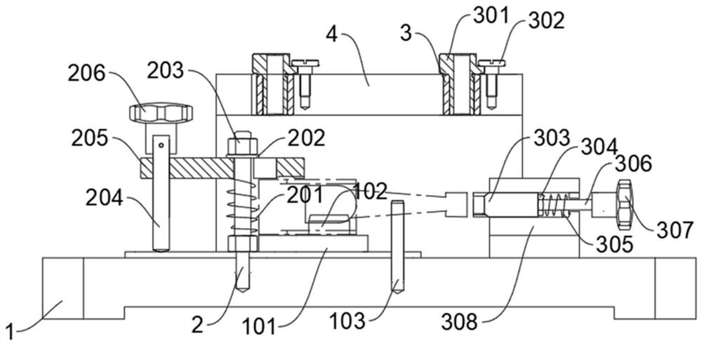
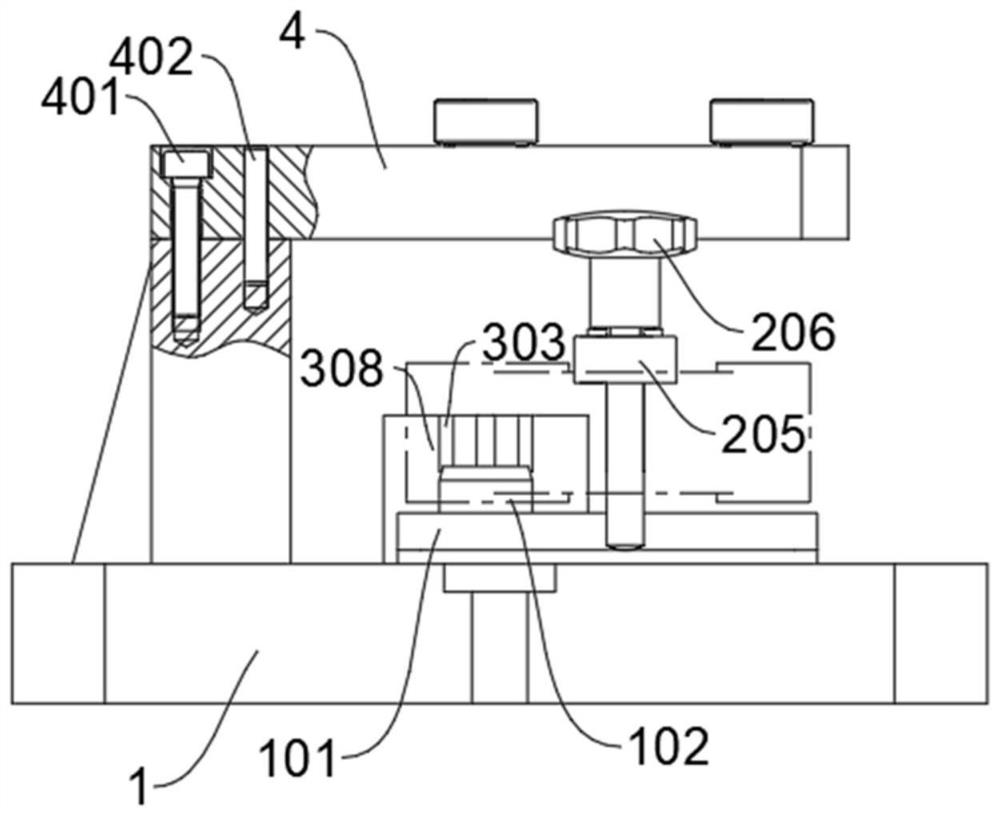
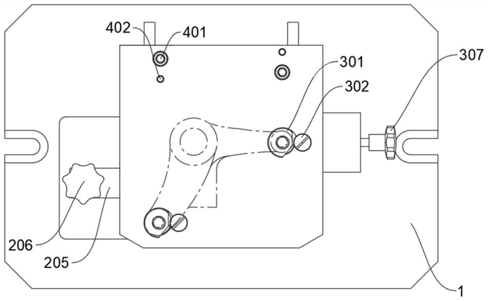
[0031] like Figure 1-4 As shown, a processing fixture for drilling a lever part includes a clamping body 1, a support plate 101 fixedly connected to the boss on the upper surface of the clamping body 1, and a vertical plate fixedly connected to the edge of the upper surface of the clamping body 1, It should be added that the middle section of the upper surface of the clamp body 1 is provided with open ear seats, so that the clamp body 1 can be fixedly connected to the workbench of the drilling machine through the open ear seats, and the upper surface of the support plate 101 is fixedly connected with The positioning pin 102, the anti-reverse pin 103 is fixedly connected to the upper surface of the clamping body 1, the upper end of the vertical plate is fixedly connected to the drilling template 4 through the inner hexagon socket head screw 401 and the cylindrical pin 402, and the drilling template 4 is connected with the drilling mechanism, the clamp The upper surface of the ...


PUM


Abstract

The invention relates to a machining fixture for drilling lever parts, which comprises a fixture body (1), a supporting plate (101) fixedly connected to the upper surface of the fixture body (1) and a vertical plate fixedly connected to the edge of the upper surface of the fixture body (1), a drill plate (4) is arranged at the upper end of the vertical plate, and the drill plate (4) is connected with a drilling mechanism; a first double-end stud (2) is arranged on the clamp body (1), and the first double-end stud (2) is connected with an external control clamping mechanism; a guide groove block (308) is arranged on the clamp body (1), and the guide groove block (308) is connected with a clamping mechanism. Compared with the prior art, six-degree-of-freedom complete positioning of the workpiece to be machined is achieved, the stability of the workpiece in the machining process is guaranteed, and therefore the machining precision and efficiency are greatly improved.

Description

technical field [0001] The invention relates to the technical field of processing fixtures, in particular to a processing fixture used for drilling a lever part. Background technique [0002] In the field of machining fixture technology, tooling fixtures are widely used in factory machining, and workpieces are usually processed by general fixtures to fix the workpiece position to achieve rough machining or finishing of the workpiece. [0003] Lever parts are commonly used parts in the mechanical field. Its function is to transmit driving force, generally including fulcrum, power arm and resistance arm. In different applications, the size and shape of levers are different, and they often need to be processed in different parts, such as punching. Holes, etc., often need to be fixed on the machine tool by lever clamps to avoid low precision due to movement during processing. At present, many lever parts are small in size and complex in structure and shape, and their dimensiona...

Claims


Application Information

Patent Timeline
22 Jul 2022
Publication
CN114770158A
IPC
B23Q3/06; B23B49/02; B23B47/00
CPC
B23Q3/062; B23B49/02; B23B47/00
Inventors
汪梦寒; 王安斌