Three-phase multi-direction grid-connected inverter

An inverter and multi-directional technology, which is applied in the field of three-phase multi-directional grid-connected inverters, can solve problems such as grid instability, three-phase unbalance, and three-phase voltage differences, and achieve high reliability, High real-time performance and the effect of eliminating resonance

Active Publication Date: 2015-03-25
武汉博日电气自动化有限公司
View PDF5 Cites 9 Cited by
  • Summary
  • Abstract
  • Description
  • Claims
  • Application Information

AI Technical Summary

Problems solved by technology

The three-phase unbalance referred to in the field of power electronics usually refers to two types of unbalance, the first is the unbalanced three-phase load, which is the three-phase unbalance referred to in the three-phase grid-connected inverter. The reason for this imbalance is that the three-phase loads connected to the output terminals of the inverter are different in size, which will cause the center point of the output voltage vector to shift, making the output voltage of each phase very different. , resulting in the so-called unbalanced three-phase output of the inverter; the second is the unbalanced three-phase power supply, which is caused by the large difference in the three-phase electromotive force connected to the power system. The difference between the three-phase voltage is very large, so the voltage between the three-phase electricity obtained by the user end is also very different, which will have a great impact on the normal power consumption of the user.
Fundamentally speaking, the imbalance of the three-phase power supply is caused by the imbalance of the three-phase load. Many electrical equipment are single-phase. The three-phase load is unbalanced, which causes the three-phase power supply to be unbalanced, resulting in the instability of the power grid

Method used


Image

  • Three-phase multi-direction grid-connected inverter
  • Three-phase multi-direction grid-connected inverter
  • Three-phase multi-direction grid-connected inverter

Examples


Embodiment Construction

[0016] The present invention will be further described in detail below with reference to the drawings and embodiments, and similar reference numerals in the drawings represent similar components.

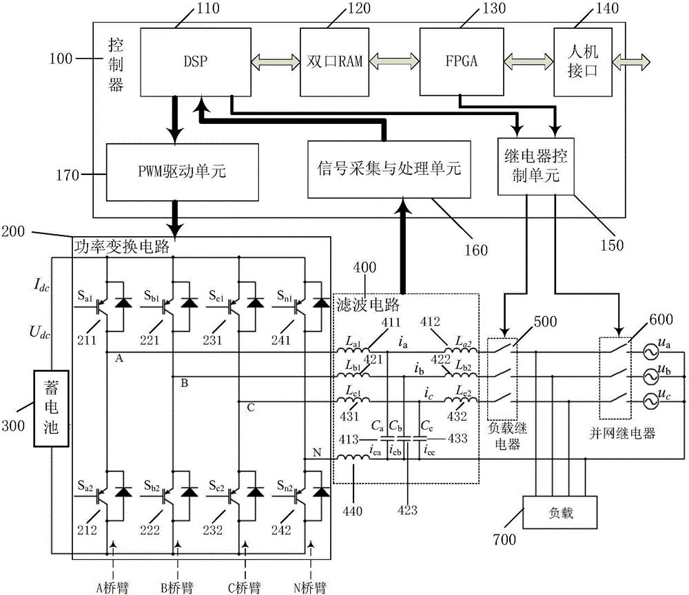
[0017] Such as figure 1 As shown, the three-phase multi-directional grid-connected inverter of the present invention includes a power conversion circuit 200 , a filter circuit 400 , a controller 100 , and the present invention is used to connect a load relay 500 , a grid-connected relay 600 and a battery 300 .

[0018] The power conversion circuit 200 includes A bridge arm, B bridge arm, C bridge arm and N bridge arm connected in parallel, the A bridge arm is composed of the first IBGT 211 and the second IGBT 212 in series, and the B, C, and N bridge arms are respectively It consists of IGBT221 and IGBT222, IGBT231 and IGBT232, and IGBT241 and IGBT242 connected in series.

[0019] One end of the first inductor 411 of phase A of the filter circuit 400 is connected to the connection ...


PUM


Abstract

The invention relates to a three-phase multi-direction grid-connected inverter which comprises a power conversion circuit, a filter circuit and a controller. The power conversion circuit comprises a bridge arm A, a bridge arm B, a bridge arm C and a bridge arm N, wherein the bridge arm A, the bridge arm B, the bridge arm C and the bridge arm N are all used for being connected with a storage battery in parallel. Each bridge arm is composed of two IGBTs in series, and the middle point A, the middle point B, the middle point C and the middle point N of all the bridge arms serve as three-phase four-wire output points of the power conversion circuit respectively. The output end of the power conversion circuit is connected with the input end of the filter circuit. The output end of the filter circuit is also the output end of the grid-connected inverter and is used for being connected with the input end of a load relay. The controller is used for collecting signals of the filter circuit, the output end of the power conversion circuit and the connection and disconnection of the load relay and a grid-connected relay. The output end of the load relay is used for being connected with loads and connected with a three-phase four-wire power grid through the grid-connected relay. The three-phase multi-direction grid-connected inverter has the advantages of being complete in function, high in utilization rate, high in real-time performance, high in reliability and the like.

Description

technical field [0001] The invention relates to an inverter, in particular to a three-phase multi-directional grid-connected inverter with the functions of grid-connected inverter, power supply for local loads and reverse charging. Background technique [0002] Energy issues have always been an important factor restricting the development of a human society. Every major progress in society is inseparable from the improvement and replacement of energy. In June 2012, the famous American economist Jeremy Rifkin proposed that the world is about to enter the "post-carbon" era, and the third industrial revolution characterized by the combination of Internet technology and renewable energy will be the The hope for sustainable development and avoiding catastrophic climate change. my country is strategically adjusting the current energy structure, vigorously researching and developing clean and renewable energy technologies, including the development and application of wind energy, ...

Claims


Application Information

Patent Timeline
Patent Type & Authority Applications(China)
IPC IPC(8): H02J3/38H02M7/5387
CPCH02J3/38H02M7/797
Inventor 陈启宏段博文全书海张立炎谢长君黄亮石英
Owner 武汉博日电气自动化有限公司
Why Eureka
Try Eureka