Vision enhancement system of camera array

A vision enhancement, camera array technology, applied in the parts of TV systems, TVs, color TVs, etc., can solve the problems of inability to meet the requirements of the image field of view, increase the cost of system construction, etc., and achieve the effect of high resolution and low cost

Active Publication Date: 2015-03-25
深圳市大族机器人有限公司
View PDF7 Cites 9 Cited by
  • Summary
  • Abstract
  • Description
  • Claims
  • Application Information

AI Technical Summary

Problems solved by technology

[0002] In some industrial applications, a single camera cannot meet the field of view requirements of the image while meeting the requirements of image a

Method used


Image

  • Vision enhancement system of camera array
  • Vision enhancement system of camera array
  • Vision enhancement system of camera array

Examples


Embodiment Construction

[0022] Now in conjunction with the accompanying drawings, the preferred embodiments of the present invention will be described in detail.

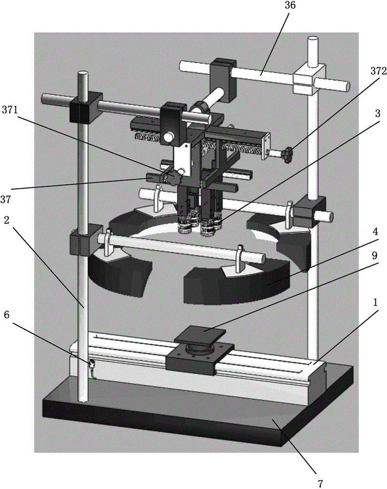
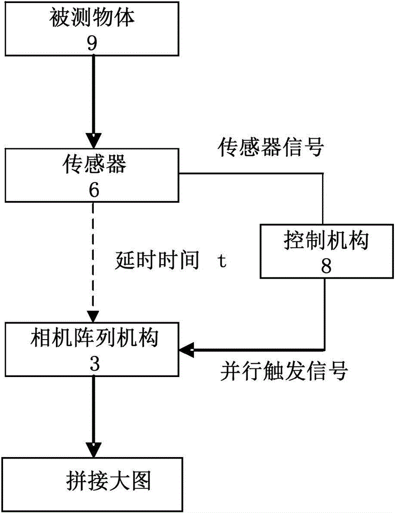
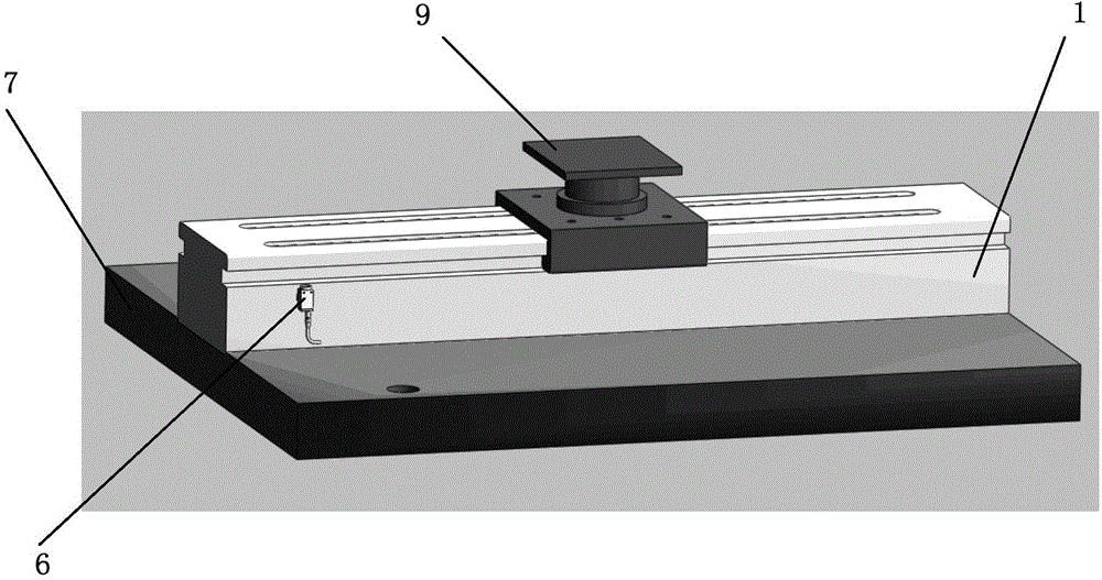
[0023] figure 1 It is a schematic structural diagram of an embodiment of the vision enhancement system of the camera array of the present invention. figure 2 It is an illustration of the working principle of the embodiment of the present invention. image 3 It is a schematic diagram of the motion process of the measured object in the embodiment of the present invention. Figure 4 It is a schematic representation of the relative positional relationship between the array camera and the measured object in the embodiment of the present invention. Figure 5 is the division of the imaging area of ​​the measured object in the embodiment of the present invention. Image 6 It is a schematic representation of the relative positional relationship between the light source and the measured object in the embodiment of the present invention.

[0024...


PUM


Abstract

The invention relates to the technical field of machine vision, in particular to a vision enhancement system of a camera array. The system comprises a transfer mechanism, a sensor, a fixed support, a light source mechanism, a camera array mechanism and a control mechanism, wherein the transfer mechanism is used for transferring a measured object to a photographing position, the sensor is used for giving a predication signal before the measured object is transferred to the photographing position, the fixed support is fixedly arranged relative to the photographing position, the camera array mechanism is fixed to the fixed support and comprises a plurality of cameras arranged oppositely, the control mechanism starts to set time in a delayed mode when acquiring the prediction signal, when set time is up, the control mechanism pushes the measured object which has been transferred to the photographing position, in other words, triggering signals are sent to the cameras, and the cameras are triggered to perform imaging on different areas of the measured object at the same time. Due to the system, a high-precision and high-definition shooting effect for a large vision field can be achieved at low cost.

Description

technical field [0001] The invention relates to the technical field of machine vision, in particular to a system for acquiring high-precision images by using an array camera. Background technique [0002] In some industrial application fields, a single camera cannot meet the field of view requirements of the image while meeting the requirements of image accuracy. Even if a high-precision, high-resolution camera meets the application requirements, it will greatly increase the construction cost of the system. Contents of the invention [0003] The technical problem to be solved by the present invention is to provide a camera array visual enhancement system for the above-mentioned defects of the prior art, which can obtain a high-precision, high-resolution shooting effect for a large field of view at a relatively low cost . [0004] The technical solution adopted by the present invention to solve the technical problem is to provide a visual enhancement system of a camera arr...

Claims


Application Information

Patent Timeline
IPC IPC(8): H04N5/225H04N5/247
Inventor 文茜王光能李玉廷舒远米野李人杰高云峰
Owner 深圳市大族机器人有限公司
Why Eureka
Try Eureka