

Acoustic transducer and microphone
一种转换器、声响的技术,应用在静电换能器传声器、半导体静电换能器、送话器口/传声器附件等方向,能够解决振动膜强度劣化等问题
- Summary
- Abstract
- Description
- Claims
- Application Information
AI Technical Summary
Problems solved by technology
Method used
Image

Examples
Embodiment approach 1
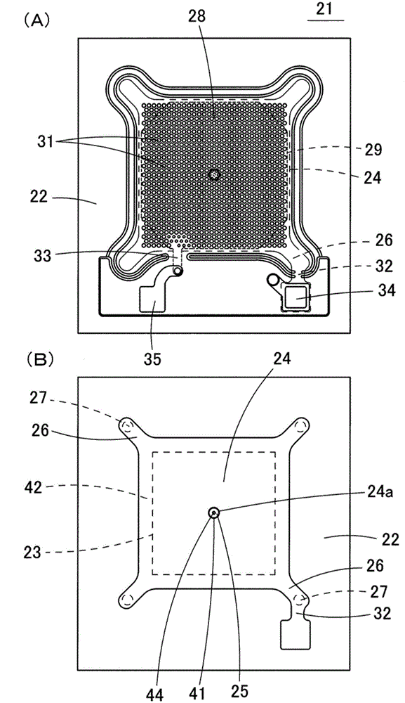
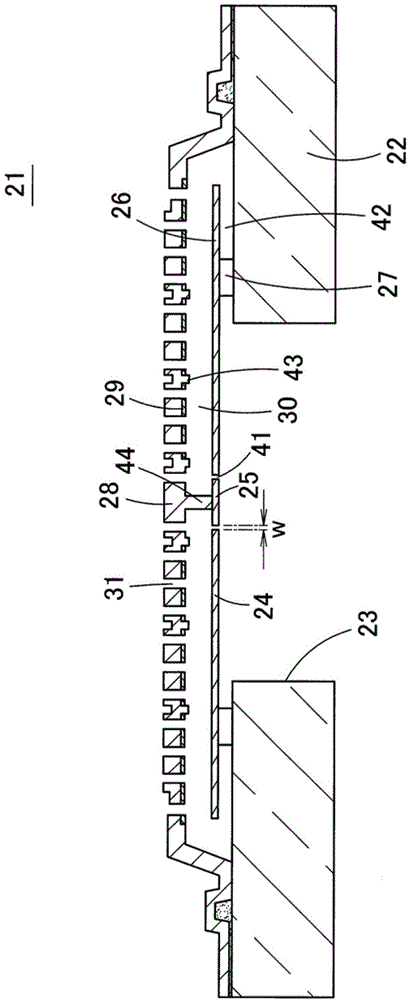
[0073] Hereinafter, the acoustic sensor 21 which is the acoustic transducer according to Embodiment 1 of the present invention will be described with reference to the drawings. Figure 4 It is an exploded perspective view of the acoustic sensor 31 which is the acoustic transducer according to Embodiment 1 of the present invention. figure 2 (A) is a plan view showing the acoustic sensor according to Embodiment 1 of the present invention. figure 2 (B) means from figure 2 The acoustic sensor shown in (A) is a plan view of a state where the back plate 28 and the fixed electrode plate 29 are removed, and the vibrating membrane 24 is exposed. image 3 is a cross-sectional view of the acoustic sensor 21 .
[0074] The acoustic sensor 21 is an electrostatic capacitive element manufactured using MEMS technology. Such as image 3 As shown, in this acoustic sensor 21 , a vibrating membrane 24 (vibrating electrode plate) is provided on a constituent substrate 32 such as a silicon s...
Embodiment approach 2
[0102] Figure 7 (A) is a schematic sectional view showing the acoustic sensor 51 according to Embodiment 2 of the present invention. Figure 7 (B) is a plan view showing an enlarged central portion of the back plate 28 of the acoustic sensor 51 .
[0103] In the acoustic sensor 51 , the plurality of support portions 44 are extended downward from the central portion of the lower surface of the back plate 28 , and the adjustment portion 25 is supported by the plurality of support portions 44 . If the adjustment part 25 is supported by a plurality of supporting parts 44, the rigidity of the adjustment part 25 becomes high, and the adjustment part 25 is not easily deformed even by a large pressure. The distance of the edge of the adjustment part 25 becomes short.
[0104] (mention about modified example)
[0105] In each of the above-mentioned embodiments, the opening 24a and the adjusting portion 25 are circular, but the opening 24a and the adjusting portion 25 may also be ...
Embodiment approach 3
[0109] Figure 10 It is a cross-sectional view showing an acoustic sensor 61 according to Embodiment 3 of the present invention, which is characterized in that a vibrating membrane 24 is provided above a fixed electrode plate 29 . In the acoustic sensor 61 , a planar back plate 28 is provided on the upper surface of the substrate 22 via an insulating layer 62 . A fixed electrode plate 29 is formed on the upper surface of the back plate 28 . Above the cavity 23 , a plurality of sound holes 31 are opened on the back plate 28 and the fixed electrode plate 29 . In addition, the vibrating membrane 24 is disposed above the back plate 28 so as to face the fixed electrode plate 29 . Foot pieces 26 extending from diaphragm 24 are supported by anchors 27 provided on top of back plate 28 .
[0110] An opening 24 a is opened in the center of the vibrating membrane 24 , and the adjustment unit 25 is arranged in the opening 24 a. The adjustment part 25 is fixed to the upper end of the s...
PUM
 Abstract
Description
Claims
Application Information