Flat speaker

Inactive Publication Date: 2011-03-22
FURUKAWA ELECTRIC CO LTD +1
View PDF11 Cites 20 Cited by
  • Summary
  • Abstract
  • Description
  • Claims
  • Application Information

AI Technical Summary

Benefits of technology

[0022]An object of the invention is to provide a flat speaker in which the disconnections in the lead portions of the voice coils hardly occur. Another object of the invent

Problems solved by technology

In the flat speaker 11 described above, there is a problem in which the amplitude of the vibrating membrane 2 becomes so large that the vibrating membrane 2 hits the permanent magnet 5, when the input power in the regeneration band in the vicinity of resonance frequency becomes large, thus generating noises or deteriorating the vibrating membra

Method used


Image

  • Flat speaker
  • Flat speaker
  • Flat speaker

Examples


Embodiment Construction

[0067]Preferable embodiments of the flat speaker of the invention are described in detail with reference to the drawings. The same numeral reference is allocated to each component having the same function to simplify the description.

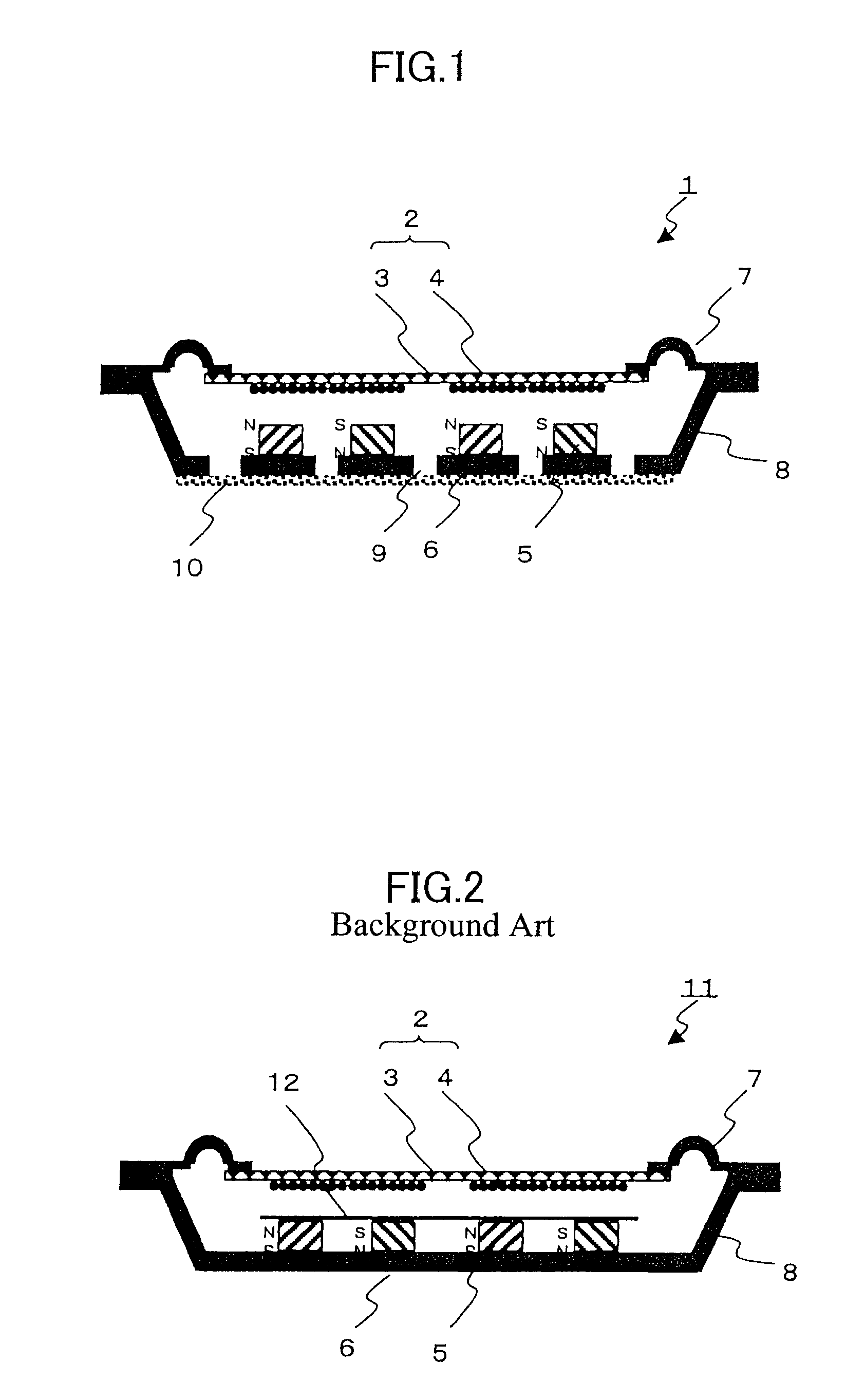
[0068]Fig.1 is a schematic sectional view of the flat speaker of one of the embodiment of the invention. Contour size of the flat speaker for example is 50 mm×80 mm.

[0069]A yoke 6 has a flat portion on which a plurality of permanent magnets are arranged 5. The plurality of permanent magnets are arranged apart with a specific distance each other and pole faces of the adjacent permanent magnets 5 are reversed each other.

[0070]A vibrating membrane 2 includes a plurality of spiral voice coils 4, and each voice coil 4 is arranged so as to face the pole face of the corresponding permanent magnet 5. The vibrating membrane 2 and the permanent magnet 5 are arranged in substantially parallel apart with a specific distance.

[0071]In this embodiment of the flat speak...


PUM


Abstract

A flat speaker comprising a vibrating plate including a spiral voice coil, a lead portion extracted from the vice coil and reinforced by the reinforcing member, and an electric supply line; an edge portion supporting the vibrating plate; and a yoke, supporting the edge portion, on which the permanent magnet arranged to face the voice coil. The flat speaker 1 of the invention includes a vibrating membrane 2 of an insulating base film 3 with a spiral or meandering voice coil 4 formed on one or both faces thereof, a permanent magnet 5 arranged on corresponding location facing the voice coil 4; and a yoke 6 on which the permanent magnet 5 is arranged. The vibrating membrane 2 is avoided from hitting the permanent magnet by providing a perforated sheet on the back face of the yoke to control acoustic resistance.

Description

BACKGROUND OF THE INVENTION[0001]1. Field of the Invention[0002]The present invention relates to a thin-type flat speaker.[0003]2. Description of the Related Art[0004]Recently information terminals are developed to be mobile style, and required to be thin, downsized, and light weighted. In order to satisfy the requirement, a flat speaker has been developed. For example, the flat speaker is developed in corresponding to the needs for a liquid crystal display television, and automobile to be thinner and light weighted.[0005]An electro-conductive flat speaker may be thinner and downsized in the construction in comparison with a corn type speaker. An example of the construction of a conventional flat speaker is described with reference to FIG. 2. FIG. 2 is a cross sectional view of the conventional flat speaker.[0006]The flat speaker depicted in FIG. 2 includes a vibrating membrane 2 with a voice coil 4 provided on one face or both faces of an insulating base film 3, a plurality of perm...

Claims


Application Information

Patent Timeline
IPC IPC(8): H04R1/00
CPCH04R9/06
Inventor NISHIMURA, TAKESHISORIMACHI, MASATONAKAJIMA, YUUZOIKEDA, HIROSHIOOTANI, KIYOSHINISHIKAWA, AKIRANAKAJIMA, YUICHISHIBATA, KIYOSEI
Owner FURUKAWA ELECTRIC CO LTD
Why Eureka
Try Eureka