Electromechanical transducer and method for manufacturing the same

a technology of electromechanical transducers and transducers, which is applied in the direction of electrical transducers, microelectromechanical systems, mechanical vibration separation, etc., can solve the problems of less displacement, and less mass and rigidity of vibrating membranes, so as to reduce displacement, reduce sensitivity, and provide more mass and rigidity

Inactive Publication Date: 2010-05-20
CANON KK
View PDF21 Cites 21 Cited by
  • Summary
  • Abstract
  • Description
  • Claims
  • Application Information

AI Technical Summary

Benefits of technology

[0009]However, if the entire surface of the capacitive electromechanical transducer is coated with the protective layer, more than sufficient mass and rigidity are provided to the vibrating membrane. Because of such an unnecessary damping effect, the vibration frequency is shifted and the amount of displacement is decreased, which may lower the sensitivity.
[0010]Accordingly, the present invention suppresses lowering of sensitivity while the protective layer is formed.
[0013]According to the present invention, a decrease in sensitivity can be suppressed while a protective layer is formed. Specifically, even if an insulating protective layer is disposed on an exposed electrode surface, the effect on the rigidity of a vibrating membrane of an electromechanical transducer can be reduced. Accordingly, a decrease in element sensitivity can be suppressed.

Problems solved by technology

However, if the entire surface of the capacitive electromechanical transducer is coated with the protective layer, more than sufficient mass and rigidity are provided to the vibrating membrane.
Because of such an unnecessary damping effect, the vibration frequency is shifted and the amount of displacement is decreased, which may lower the sensitivity.

Method used


Image

  • Electromechanical transducer and method for manufacturing the same
  • Electromechanical transducer and method for manufacturing the same
  • Electromechanical transducer and method for manufacturing the same

Examples


example 1

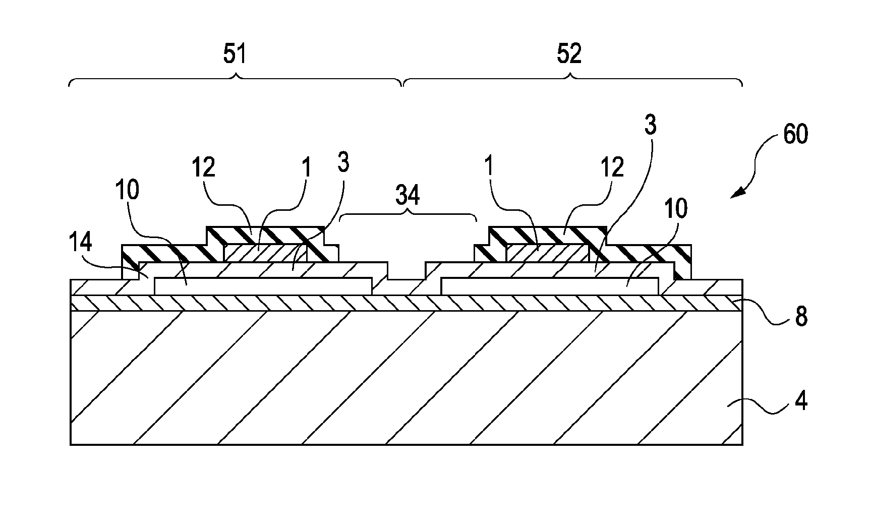
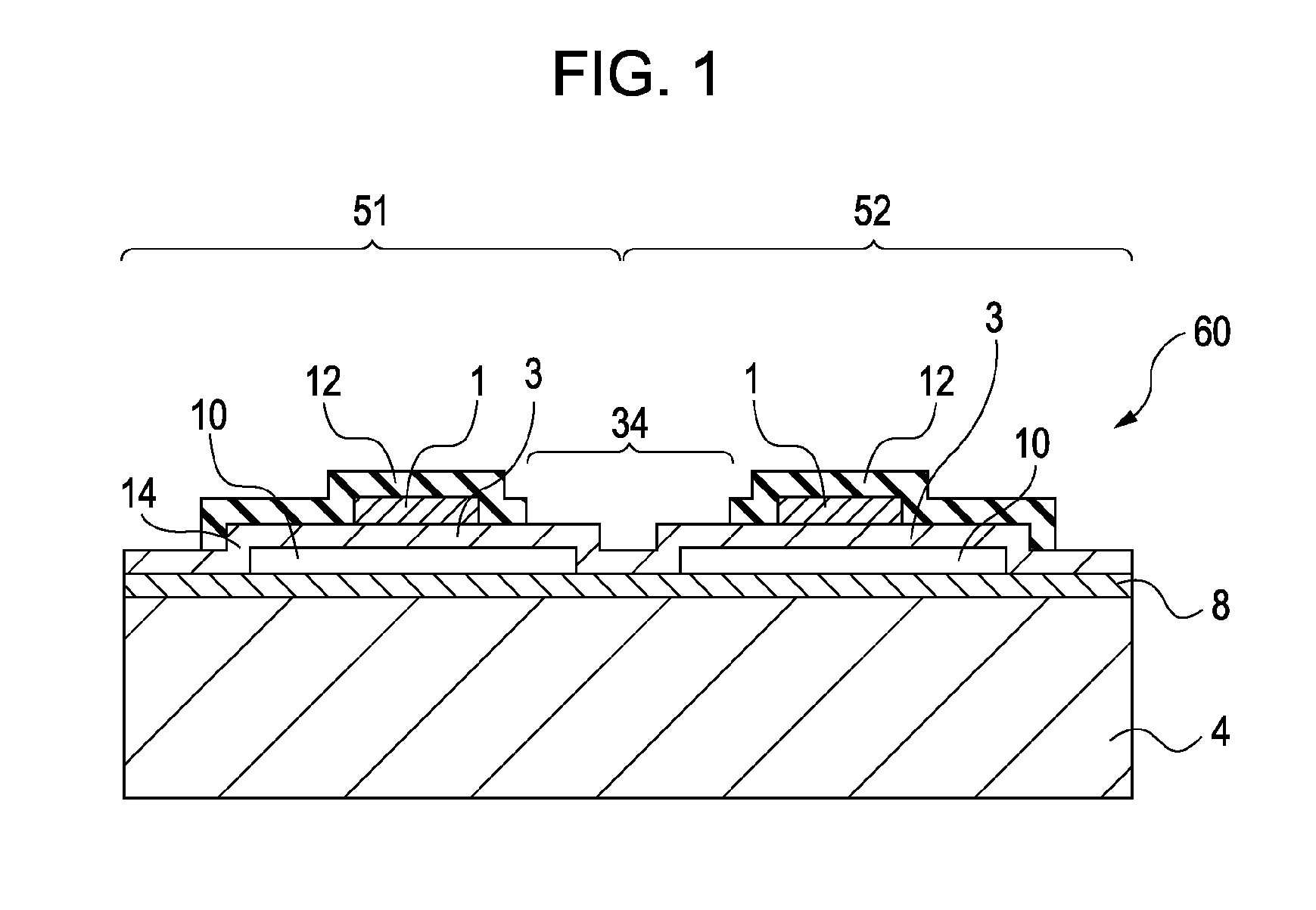
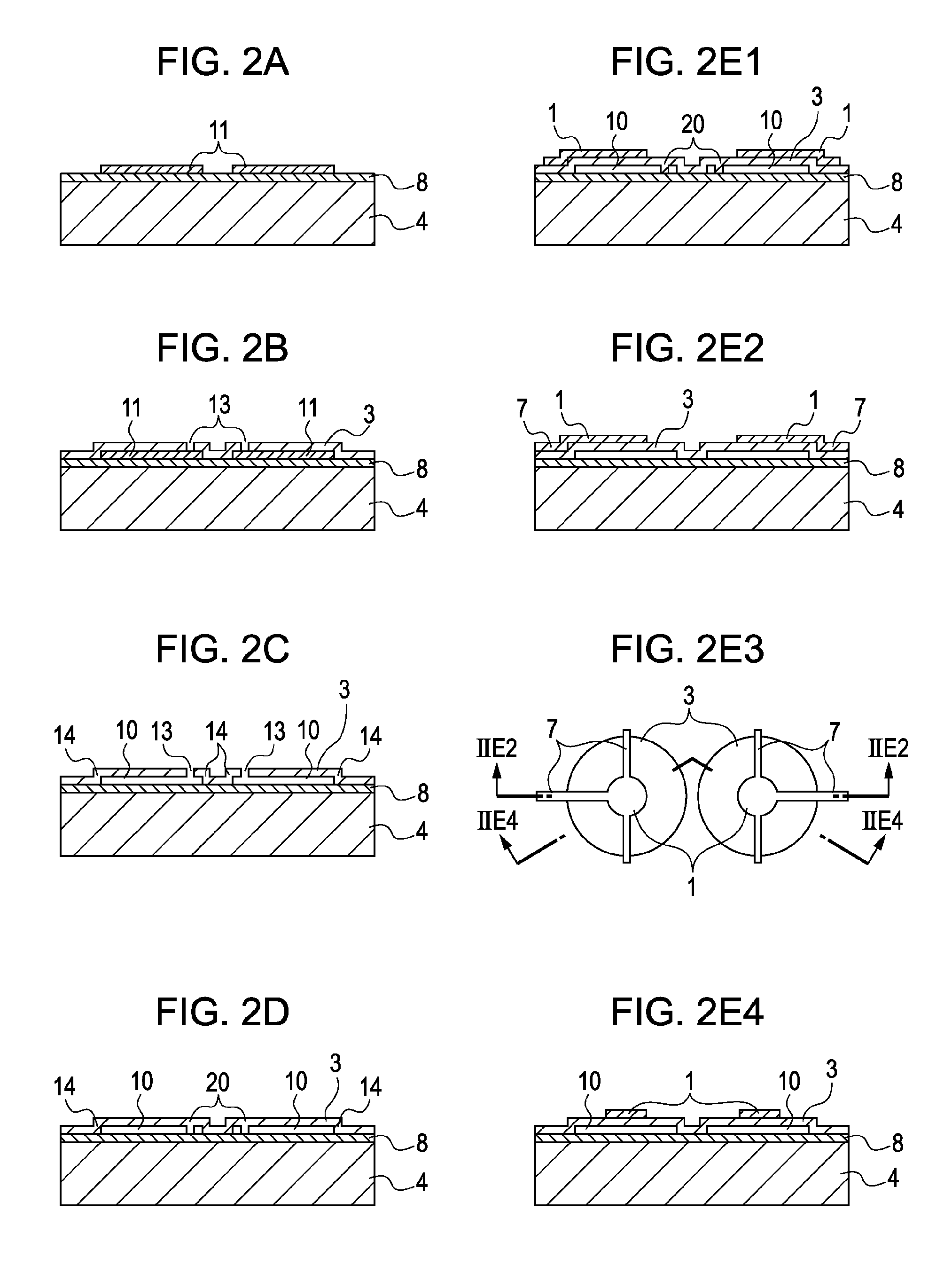
[0036]FIGS. 2A to 2E2 and 2E4 and 2E3 are respectively sectional views and a top view describing the steps of Example 1 of a method for manufacturing the electromechanical transducer according to the present invention. To simplify the following description, a patterning step means all steps that include a photolithography step including application of a photoresist to a substrate, drying, exposure, and development; an etching step; a step of removing the photoresist; a step of cleaning the substrate; and a drying step performed in sequence. Although a substrate 4 of this Example is composed of Si as an example, a substrate composed of another material can be used. For instance, an insulating substrate composed of SiO2 or sapphire can be used. FIGS. 2A to 2E2 and 2E4 and 2E3 are respectively sectional views and a top view in which two elements adjacent to each other are formed. However, the number of elements is not limited to two, and any number of elements can be formed using the s...

example 2

[0055]In this Example, an electromechanical transducer is manufactured by the same method as that of Example 1 until the steps shown in FIGS. 2A to 2E4. Subsequently, a protective layer is patterned as shown in a top view of FIG. 5. The protective layer is composed of photosensitive polyimide (e.g., photosensitive polyimide available from Toray Industries, Inc., Product name: Photoneece). With such a material, the protective layer can be directly patterned by precise lithography. Thus, an electromechanical transducer can be easily manufactured compared with the case where an electromechanical transducer is manufactured by the etching method described in Example 1.

[0056]In this Example, the protective layer 12 between the upper electrodes of the two elements adjacent to each other (first element 51 and second element 52) is completely removed as shown in FIG. 5. The larger the distance 2g is, the more the crosstalk of the elements adjacent to each other can be suppressed.

example 3

[0057]In this Example, an electromechanical transducer is manufactured by the same method as that of Example 1 until the steps shown in FIGS. 2A to 2E4. Subsequently, a protective layer 12 is patterned as shown in a top view of FIGS. 6A and 6B. FIG. 6B is a perspective view and the protective layer 12 of FIG. 6A is shown in perspective in FIG. 6B.

[0058]A thermosetting resin (e.g., Product name: OGSOL SI-20 available from Osaka Gas Chemicals Co., Ltd.) is applied as the protective layer. Subsequently, an electrical signal is extracted from the upper electrode 1 through a line 33, the line 33 being connected to an external current source 32. When an electric current is applied to two ends of the upper electrode 1, the upper electrode 1 itself functions as a resistance wire and generates heat. Consequently, the thermosetting resin near the upper electrode can be cured. Particularly when the vibrating membrane 3 is a poor thermal conductor, for example, a nitride film SiNX, the heat is ...


PUM

PropertyMeasurementUnit
sheet resistanceaaaaaaaaaa

Abstract

An electromechanical transducer of the present invention includes a first electrode, a vibrating membrane formed above the first electrode through a gap, a second electrode formed on the vibrating membrane, and an insulating protective layer formed on a surface of the second electrode side. A region where the protective layer is not formed is present on at least part of a surface of the vibrating membrane.

Description

BACKGROUND OF THE INVENTION[0001]1. Field of the Invention[0002]The present invention relates to an electromechanical transducer and a method for manufacturing the electromechanical transducer.[0003]2. Description of the Related Art[0004]Capacitive electromechanical transducers manufactured using a micromachining step have been actively investigated in recent years. A typical capacitive electromechanical transducer includes a lower electrode as a first electrode, a vibrating membrane supported so as to maintain a certain distance between the vibrating membrane and the lower electrode, and an upper electrode disposed on a surface of the vibrating membrane. Such a capacitive electromechanical transducer is used as, for example, a capacitive micromachined ultrasonic transducer (CMUT).[0005]A CMUT can transmit and receive ultrasonic waves using a lightweight vibrating membrane and has good wideband characteristics in the liquid and air. Thus, a CMUT receives attention as an up-and-comin...

Claims


Application Information

Patent Timeline
Patent Type & Authority Applications(United States)
IPC IPC(8): H02N11/00H04R31/00
CPCB06B1/0292H04R19/005Y10T29/49005Y10T29/49007H04R31/00B81C1/00158B81B2201/0285H04R2201/003
Inventor CHANG, CHIENLIU
Owner CANON KK
Why Eureka
Try Eureka