Punching equipment

A punching die and punching device technology, applied in the field of punching processing equipment, can solve the problems of inconvenient adjustment of the position and distance between a feeding device and a punching machine, heavy weight, and high requirements.

Inactive Publication Date: 2015-04-01
NINGBO ZHENHAI XIUYANG ADVERTISEMENT DECORATION
View PDF0 Cites 6 Cited by
  • Summary
  • Abstract
  • Description
  • Claims
  • Application Information

AI Technical Summary

Problems solved by technology

[0004] The traditional feeding device generally includes a machine base, a coiler arranged on the machine base, and a strip coil wound on the coiler. The coiler can rotate around the rotating shaft. The roller conveying device conveys the strip coil wound on the coiler to the stamping position of the punching machine. The coiler can be driven and rotate around the rotating shaft, and the waste strip after stamping is coiled by the receiving device. Recycling; when the punching machine is working, the roller conveying device on the punching machine will transport the strip material coiled on the coiler to the stamping position of the punching machine, and the coiler can be driven and rotate around the shaft. The device is driven to rotate, so the requirements for the roller conveying device are relatively high, and there must be a large pulling force to pull the strip material. Once the pulling force is insufficient or slips, the strip material at the punching place of the punching machine cannot be kept up synchronously, resulting in punching Failure; the feeding device in the prior art generally has a fixed frame, which is very inconvenient to carry, and when the feeding device is loaded with strip coils, the weight is relatively large, and it is inconvenient to adjust the position and position between the feeding device and the punching machine. spacing, so there is still room for improvement

Method used


Image

  • Punching equipment
  • Punching equipment
  • Punching equipment

Examples


Embodiment Construction

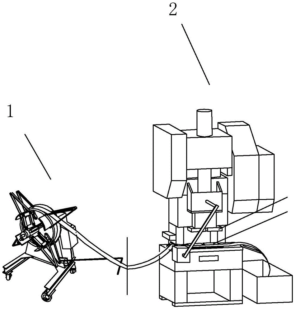
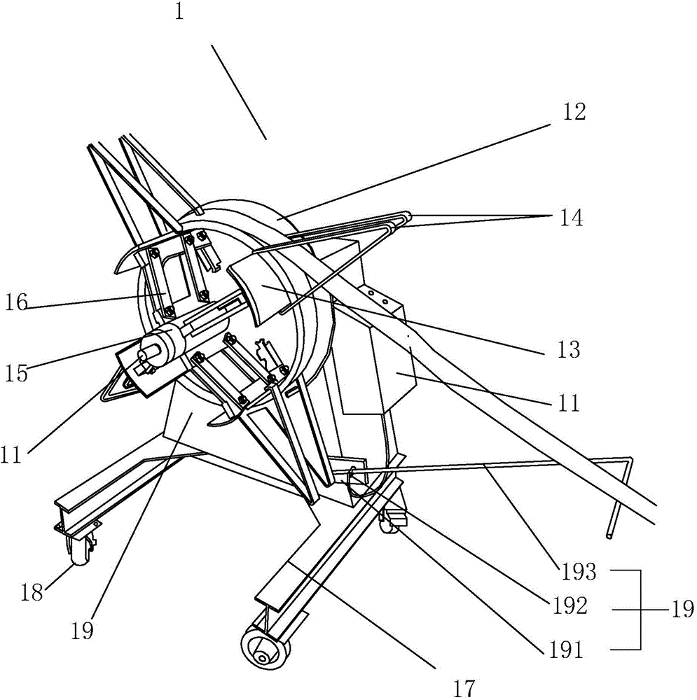
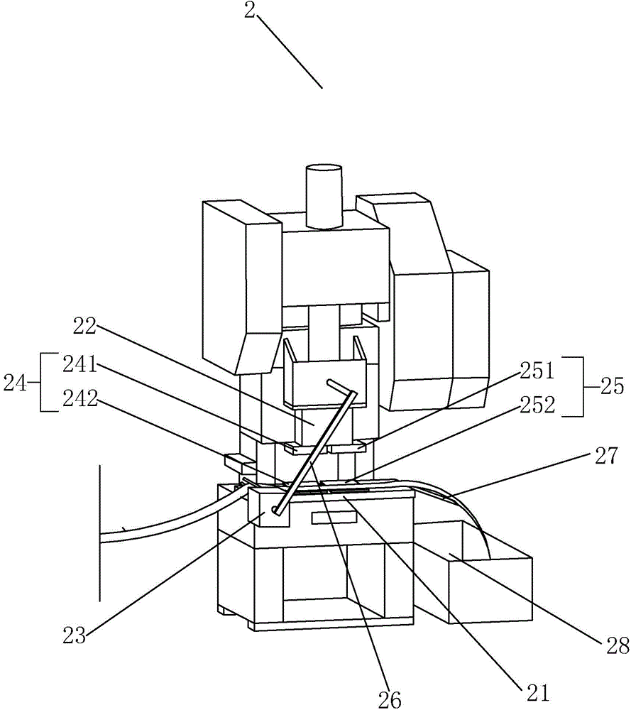
[0021] refer to Figure 1 to Figure 3 The embodiment of the punch press equipment of the present invention will be further described.

[0022] A kind of stamping equipment, comprises feeding device 1 and punching machine 2 that are arranged in sequence, feeding device 1 comprises machine base 10, and machine base 10 is provided with rotating shaft 11 and coiler that coils for strip material winding, rotating shaft 11 and coiling The coiler is coaxially arranged, and the coiler includes a fixed baffle 12 and a number of movable baffles 13 that can be wound around the strip coil. The retaining bar 14, the base 10 bottom is provided with a chassis 17, the chassis 17 is provided with a roller, the base 10 is provided with an induction device 19 and a stepping motor 100 linked with the rotating shaft 11, the induction device 19 and the stepping motor 100 electrical connections.

[0023] By adopting the above-mentioned technical scheme, the stamping equipment includes a feeding de...


PUM


Abstract

The invention discloses punching equipment. The punching equipment comprises a material delivery device and a punch press which are sequentially arranged. The punching equipment is characterized in that the material delivery device comprises a machine seat, wherein a rotary shaft and a coiling device are arranged on the machine seat, the coiling device is used for winding strip coils, the rotary shaft and the coiling device are coaxially arranged, the coiling device comprises a fixed retaining plate and a plurality of movable retaining plates, the movable retaining plates are used for winding the strip coils, retaining strips are arranged at the two sides of each strip coil on the corresponding movable retaining plate and are used for respectively limiting the corresponding strip coil, a bottom frame is arranged at the bottom part of the machine seat, rollers are arranged under the bottom frame, a sensing device and a stepping motor are arranged on the machine seat, the stepping motor is linked with the rotary shaft, and the sensing device is electrically connected with the stepping motor. The punching equipment has the advantages that by arranging the material delivery device which can synchronously work, the handling and position adjusting of the material delivery device are convenient, the strip coils can be actively conveyed, the influence on the punching process caused by the untimely material delivery is avoided, and the production and processing properties of the equipment are effectively improved.

Description

technical field [0001] The present invention relates to a stamping processing equipment, more specifically, it relates to a stamping equipment. Background technique [0002] A punching machine is a stamping press. In national production, the stamping process saves materials and energy compared with traditional machining, has high efficiency, does not require high technical requirements for operators, and can be machined through various mold applications. These advantages of products that cannot be achieved, so its use is becoming more and more extensive. [0003] Stamping equipment in the prior art generally includes a feeding device and a punching machine arranged in sequence; the feeding device is used to load strip coils and continuously provide strip coils for the punch press; when the strip coils are transported to the stamping place, the Punch for processing. [0004] The traditional feeding device generally includes a machine base, a coiler arranged on the machine b...

Claims


Application Information

Patent Timeline
Patent Type & Authority Applications(China)
IPC IPC(8): B21D43/05B21D43/20
CPCB21D43/05B21C47/3416B21C47/3433B21C47/345
Inventor 王大海
Owner NINGBO ZHENHAI XIUYANG ADVERTISEMENT DECORATION
Why Eureka
Try Eureka