
A steel clip automatic feeding device

A technology of automatic feeding and steel clips, applied in metal processing, metal processing equipment, manufacturing tools, etc., can solve problems such as backward technology, low production efficiency, tight or loose buckling of steel clips and U disks, etc., to reduce production cost, increase production efficiency, and unify standards

Active Publication Date: 2017-01-25
SHENZHEN OSCOO TECH
View PDF8 Cites 0 Cited by
  • Summary
  • Abstract
  • Description
  • Claims
  • Application Information

AI Technical Summary

Problems solved by technology

At present, the production of this kind of U disk is produced by manual assembly line operation. The workers align the U disk body with the assembly hole of the steel clip. When the worker pre-presses and expands the steel clip, the angle is often not in place, causing the steel clip to be damaged. The buckle with the U disk is tight or loose, which seriously affects the product quality and production efficiency. Not only the technology is backward, the production efficiency is low, and the production cost is increased; but also due to manual operation errors, the quality standards of the products are not uniform, and the supervision is difficult.

Method used


Image

  • A steel clip automatic feeding device
  • A steel clip automatic feeding device
  • A steel clip automatic feeding device

Examples


Embodiment Construction

[0026] It should be noted that, in the case of no conflict, the embodiments in the present application and the features in the embodiments can be combined with each other. The present invention will be further described below in conjunction with the accompanying drawings.

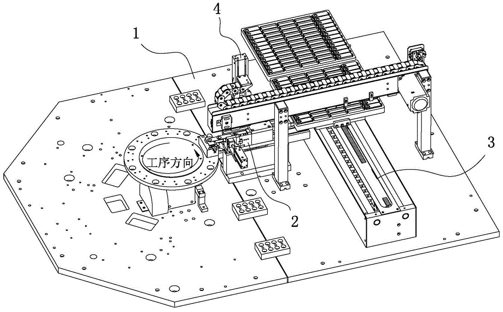
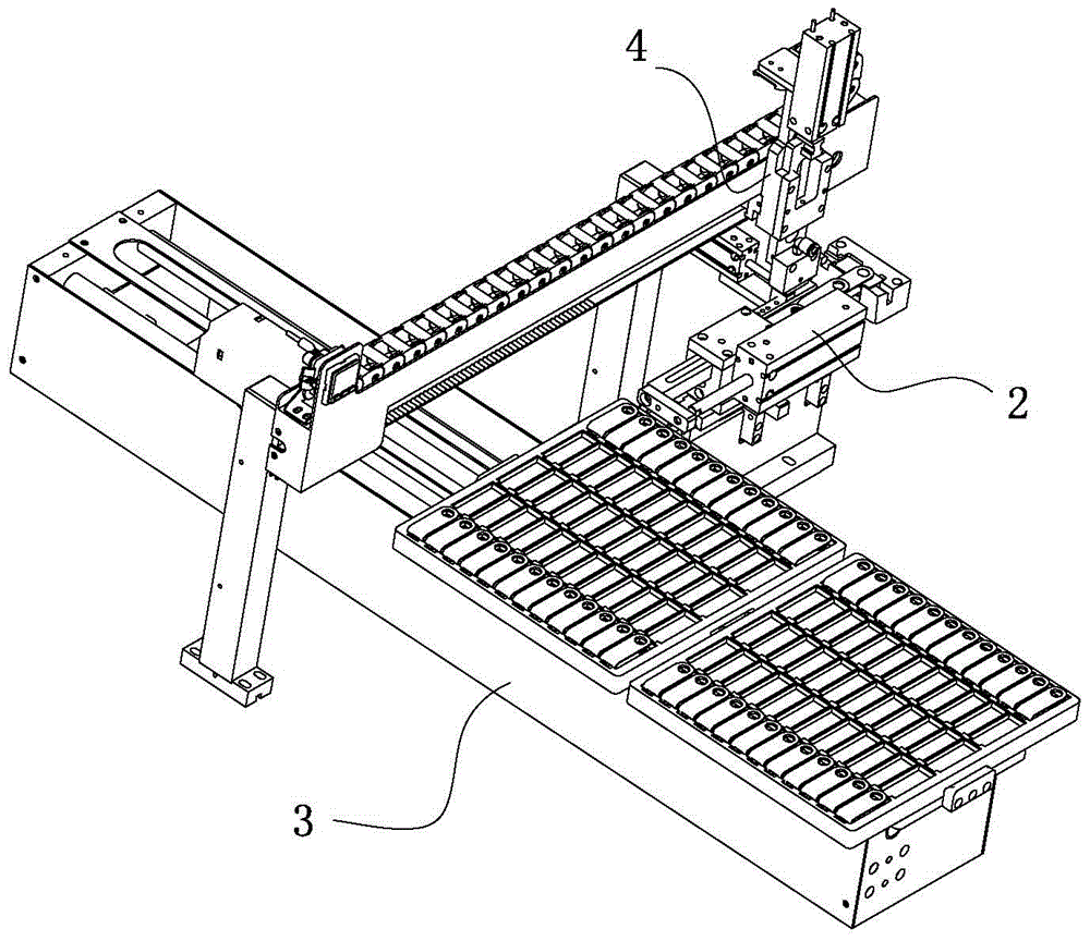
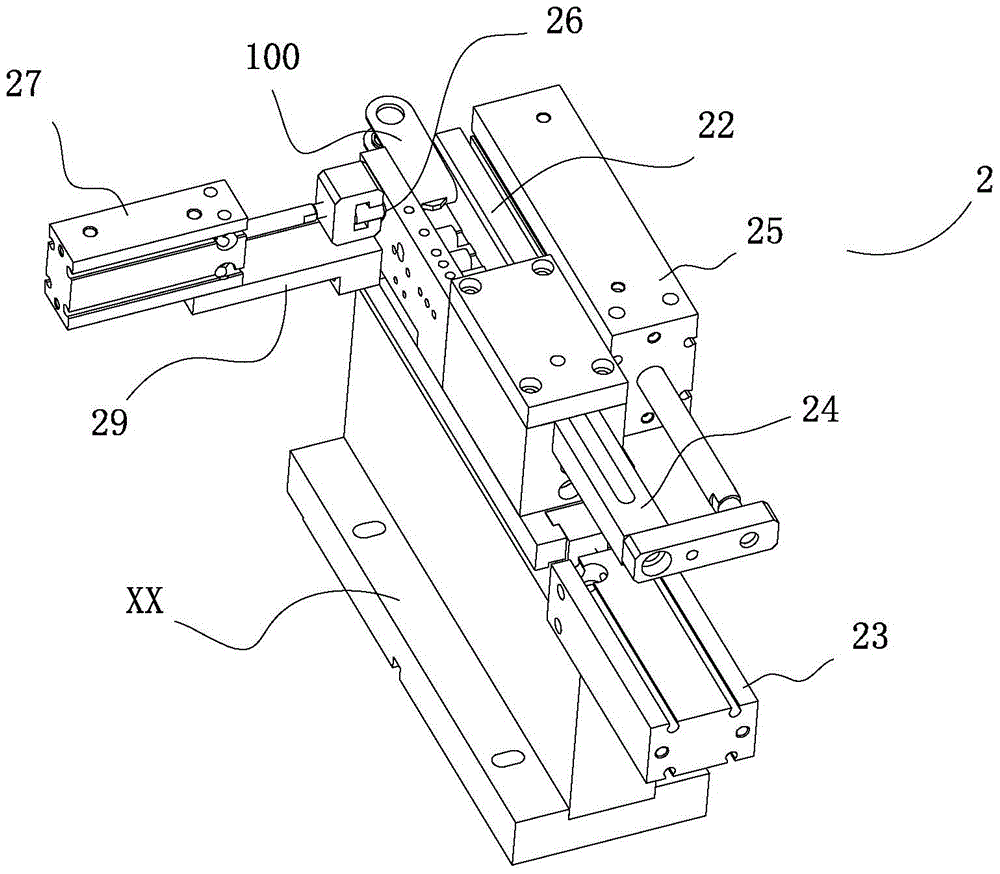
[0027] Such as figure 1 , figure 2 As shown, the steel clip automatic feeder base plate 1 of the embodiment of the present invention, the pushing mechanism 2 arranged on the base plate 1, the loading mechanism 3 for loading the steel clip 100, the loading mechanism 3 for loading the steel clip 100 from the loading mechanism 3 transported to the take-up mechanism 4 on the push mechanism 2, such as image 3 , Figure 4 As shown, the pusher mechanism 2 includes a base XX fixedly installed on the base plate 1, a pusher groove 22 slidably arranged on the top of the base XX, and a first pusher groove 22 fixedly arranged on the base XX for pushing the pusher groove 22 to slide. Pushing material cylinder 23; O...


PUM


Abstract

An automated steel-housing feeding apparatus comprises a bottom plate (1), a conveying mechanism (2) disposed on the bottom plate (1), a loading mechanism (3) for loading steel housings (100), and a fetching mechanism (4) for transporting the steel housings (100) from the loading mechanism (3) to the conveying mechanism (2). The conveying mechanism (2) comprises a base (21) fixedly mounted on the bottom plate (1), a conveying groove (22) slideably disposed at the top end of the base (21), and a first driving cylinder (23) fixedly disposed on the base (21) and used for driving the conveying groove (22) to slide. A pushing rod (24) is slideably disposed at one end of the conveying groove (22), and a second driving cylinder (25) for driving the pushing rod (24) to slide in a reciprocating way is fixedly disposed on the side wall of the conveying groove (22). A passage (26) is provided on the side wall of the other end of the conveying groove (22), an expanding cylinder (27) is fixedly mounted on the side wall of the conveying groove (22), and an expansion jig (28) is fixedly mounted at the telescopic end of the expanding cylinder (27). The apparatus ensures that steel housings can be expanded within a very small range of angles, which helps to produce uniform standard products, greatly improves the production efficiency, and lowers production costs.

Description

technical field [0001] The invention relates to the U disk manufacturing technology, in particular to an automatic feeding device for steel clips. Background technique [0002] In real life, there are many kinds of U disks, and one of the widely used U disks is to open the U disk by rotating the steel clip on the U disk. At present, the production of this kind of U disk is produced by manual assembly line operation. The workers align the U disk body with the assembly hole of the steel clip. When the worker pre-presses and expands the steel clip, the angle is often not in place, causing the steel clip to be damaged. The buckle with the U disk is tight or loose, which seriously affects the product quality and production efficiency. Not only is the technology backward, the production efficiency is low, and the production cost is increased; but also due to manual operation errors, the quality standards of the products are not uniform, and the supervision is difficult. Therefore...

Claims


Application Information

Patent Timeline
Patent Type & Authority Patents(China)
IPC IPC(8): B23P19/00
CPCB23P19/00
Inventor 尹春胡朝阳
Owner SHENZHEN OSCOO TECH
Learn More