
Solid electrolytic capacitor and its manufacturing method

A manufacturing method and solid electrolyte technology, applied in solid electrolytic capacitors, electrolytic capacitors, capacitors, etc., can solve the problems of incorrect anode lead frame position accuracy, deterioration of connection strength, poor tightness, etc., to achieve easy operation and improve ESP characteristics , the effect of improving welding strength

Inactive Publication Date: 2011-06-01
SANYO ELECTRIC CO LTD
View PDF2 Cites 0 Cited by
  • Summary
  • Abstract
  • Description
  • Claims
  • Application Information

AI Technical Summary

Problems solved by technology

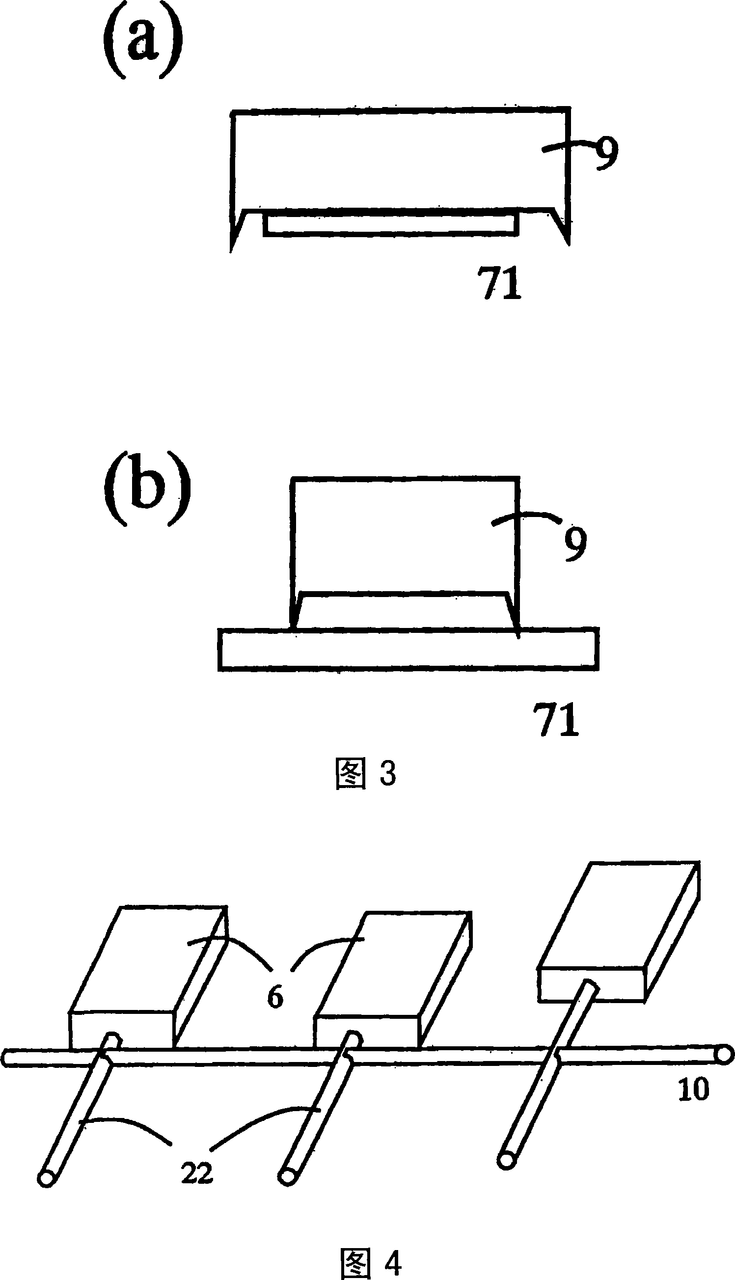
Cutting when forming by the pillow forms spikes (bari) below the pillow, so the width of the pillow is smaller than the lead frame width, as shown in Figure 3 (b), the pillow (9) and the anode lead frame ( 71) There is a gap between them, and the adhesion is poor, so there is a problem that the connection strength deteriorates and the connection cannot be made
[0008] As shown in Figure 4, pillows are formed in multiple capacitor elements at the same time, so the positions of each cannot be adjusted, and the position accuracy of the anode lead frame is not correct, and there are problems in the alignment of laser welding, etc.

Method used


Image

  • Solid electrolytic capacitor and its manufacturing method
  • Solid electrolytic capacitor and its manufacturing method
  • Solid electrolytic capacitor and its manufacturing method

Examples


Embodiment Construction

[0026] Embodiments of the present invention will be described below.

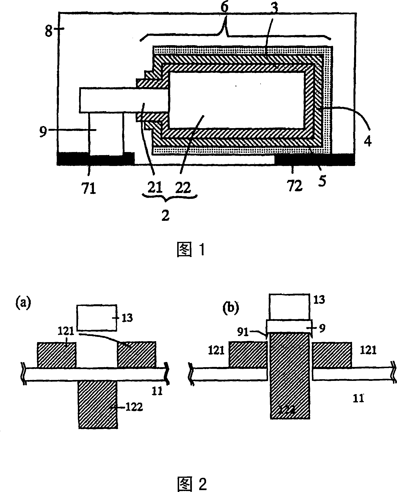
[0027] FIG. 1 is a cross-sectional view of a solid electrolytic capacitor according to an embodiment of the present invention. The solid electrolytic capacitor comprises a capacitor element (6) and a pillow (9) provided between the capacitor element (6) and the anode lead frame (71), and the anode lead frame (71) and the cathode lead frame (72) The lower part of the body is covered with exterior resin (8) in a state where it is exposed.

[0028] The above-mentioned capacitor element (6), as its manufacturing process, is formed by sequentially forming a dielectric oxide film (3) and a cathode composed of a solid electrolyte on the outer peripheral surface of the sintered body (22) made of a valve action metal from which the anode lead (21) is drawn out. layer (4), silver paste (paste) or carbon cathode lead-out layer (5).

[0029] Here, the so-called valve action metal refers to a metal that forms an extre...


PUM


Abstract

To provide a method for manufacturing a solid electrolytic capacitor in which a pillar member used for connection of an anode lead and an anode lead frame exhibits excellent adhesion to the anode lead frame at the time of bonding, and positioning to the lead frame is performed with high precision. A rudder-like frame is employed as a pillar member, and a pillar portion wider than the width of theanode lead frame is cut in the direction perpendicular to the lead-out direction of the anode lead. The pillar portion is positioned while being chucked, and bonded to the anode lead frame.

Description

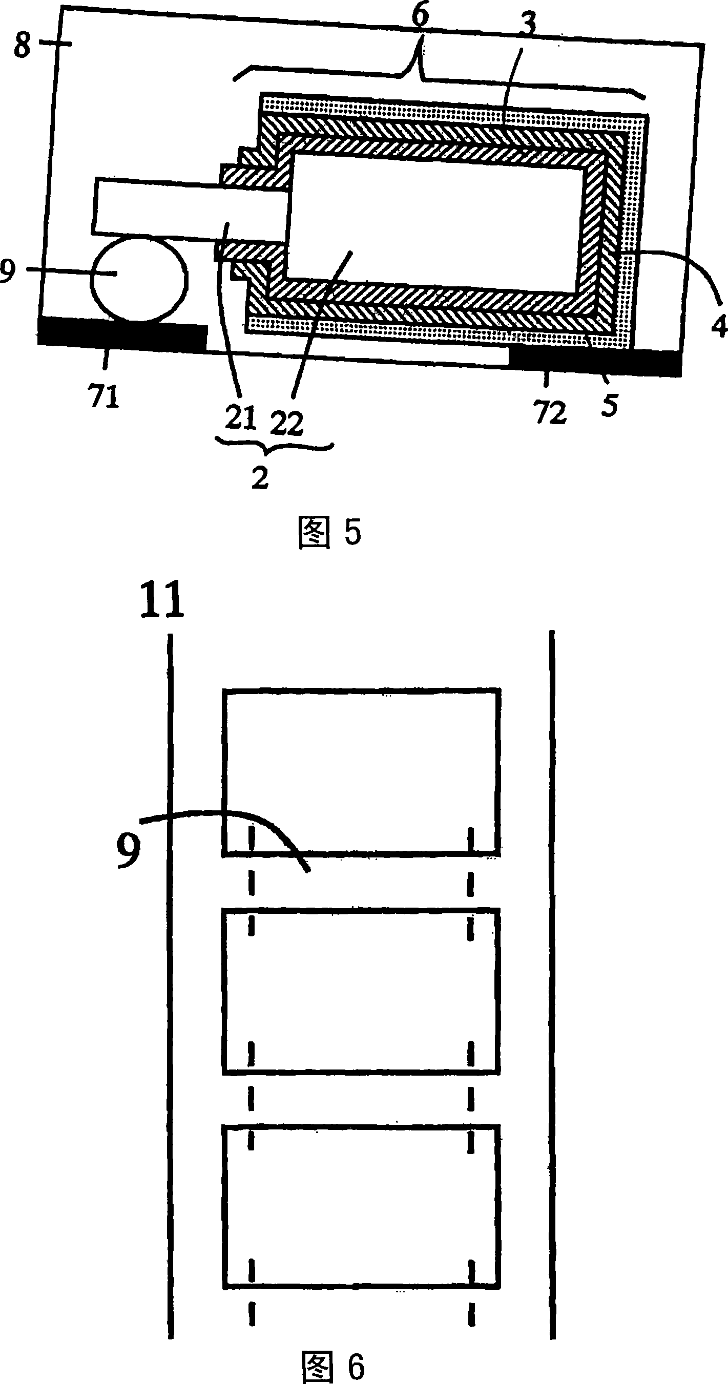
technical field [0001] The present invention relates to a solid electrolytic capacitor and a method of manufacturing the same. Background technique [0002] Fig. 5 is a sectional view of a conventional solid electrolytic capacitor (1). The solid electrolytic capacitor (1) includes a capacitor element (6) on which an anode lead frame (71) and a cathode lead frame (72) are mounted below, and the capacitor element (6) is covered with a synthetic resin (8). A capacitor element (6) is formed by sequentially forming a dielectric oxide film (3), a cathode layer (4), and a cathode lead-out layer (5) on the outer peripheral surface of a valve metal sintered body (22). Here, the term "valve metal" refers to a metal that forms an extremely dense and durable dielectric oxide film (3) by electrolytic oxidation treatment, and specifically refers to tantalum, niobium, aluminum, titanium, and the like. [0003] An anode lead (21) formed of a valve metal protrudes from a central portion in...

Claims


Application Information

Patent Timeline
Patent Type & Authority Patents(China)
IPC IPC(8): H01G9/00H01G9/012
CPCH01G9/15H01G9/012Y10T29/435H01G9/00
Inventor 藤井永造井原勇俊高桥裕辅笠原武志平松克巳
Owner SANYO ELECTRIC CO LTD
Learn More