Shock-resistant and noise-reducing reciprocating piston compressor

A reciprocating and compressor technology, applied in the field of reciprocating piston compressors, can solve the problems of damage to the piston cylinder, reduce the service life of the piston cylinder and the piston, easy to generate heat, etc., and achieve the effect of reducing noise and ensuring close contact

Pending Publication Date: 2022-04-05
BENGBU AUTO COMPRESSOR
View PDF1 Cites 0 Cited by
  • Summary
  • Abstract
  • Description
  • Claims
  • Application Information

AI Technical Summary

Problems solved by technology

[0004] Because the existing reciprocating piston compressor compresses the gas through the piston and piston cylinder, it is very prone to vibration and wear, which makes the reciprocating piston compressor generate a lot of noise during the working process, and reduces the friction between the piston cylinder and the piston. service life, and it is easy to damage the reciprocating piston compressor due to vibration and wear. During the working process of the reciprocating piston compressor, it is very easy to generate heat due to the vibration and wear between the piston and the piston cylinder, so it is also necessary to dissipate heat from the piston cylinder. However, the existing reciprocating piston compressors cannot take into account both noise reduction and heat dissipation. When the noise is silenced, the piston cylinder is often damaged due to the inability to dissipate heat quickly. There is also friction, resulting in a limited lifespan for reciprocating piston compressors

Method used


Image

  • Shock-resistant and noise-reducing reciprocating piston compressor
  • Shock-resistant and noise-reducing reciprocating piston compressor
  • Shock-resistant and noise-reducing reciprocating piston compressor

Examples


Embodiment Construction

[0036] In order to further explain the technical means and effects of the present invention to achieve the intended purpose of the invention, the specific implementation, structure, features and effects of the present invention will be described in detail below in conjunction with the accompanying drawings and preferred embodiments.

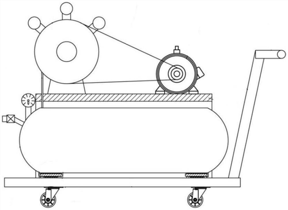
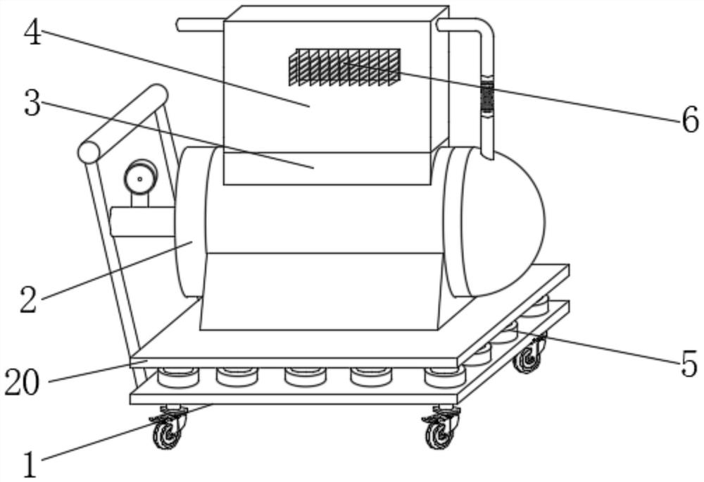
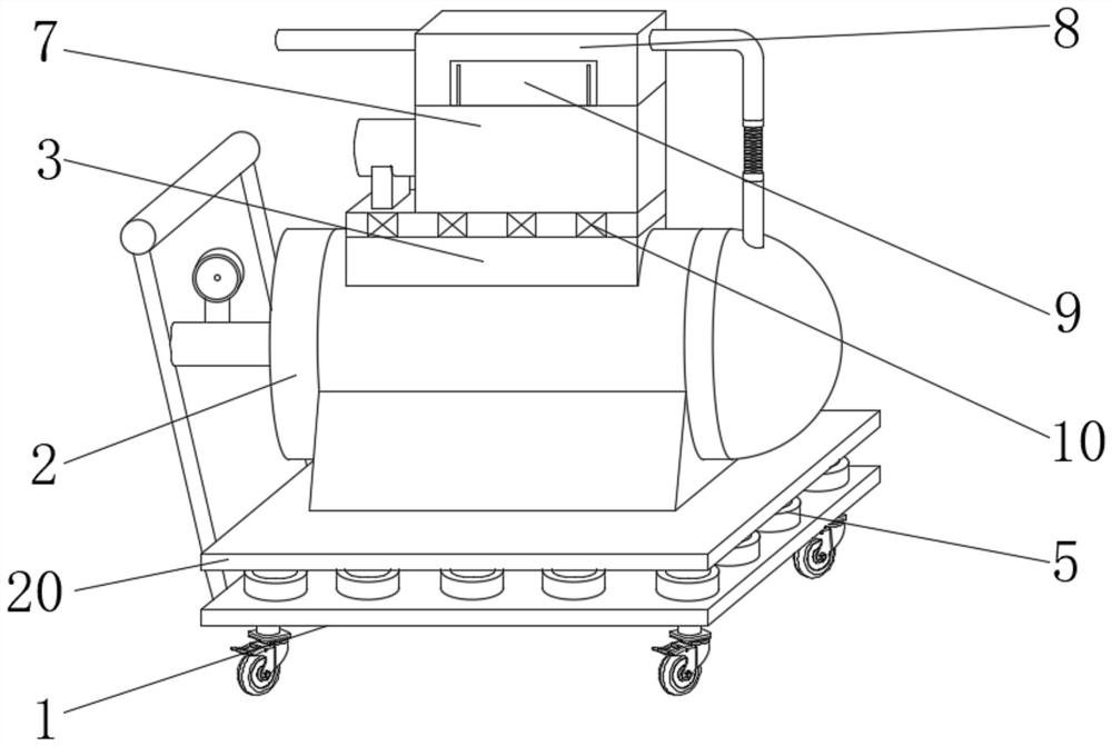
[0037] see Figure 2-10 Shown: an anti-seismic and sound-absorbing reciprocating piston compressor, including a transfer car 1 and an air storage tank 2, the lower part of the outer circumference of the air storage tank 2 is provided with a mounting base, the upper surface of the transfer car 1 is equipped with a support plate 20, and the transfer car 1 and the support plate 20 are installed with a number of shock-absorbing telescopic rods 5 evenly distributed in an array, the installation base of the gas storage tank 2 is fixedly connected to the middle part of the upper surface of the support plate 20, and the outer peripheral upper part of the ...


PUM


Abstract

The invention relates to an anti-vibration and noise-reduction reciprocating piston compressor which comprises a transfer trolley and an air storage tank, a mounting base is arranged on the lower portion of the periphery of the air storage tank, a supporting plate is mounted on the upper surface of the transfer trolley, and a plurality of damping telescopic rods which are evenly distributed in an array mode are mounted between the transfer trolley and the supporting plate; a mounting base of the air storage tank is fixedly connected to the middle of the upper surface of the supporting plate, a supporting base is fixedly connected to the upper portion of the periphery of the air storage tank, a gear box is mounted on the outer surface of the upper end of the supporting base, a plurality of damping springs evenly distributed in an array mode are mounted between the gear box and the supporting base, and a power motor is mounted on one side of the gear box. The upper side of the gearbox is fixedly connected and communicated with a plurality of piston cylinders which are evenly distributed at equal intervals, the outer surface of the upper end of the gearbox is fixedly connected with a heat dissipation box covering the outer sides of the piston cylinders, and a sound insulation box covering the outer sides of the gearbox, the heat dissipation box and the power motor is installed on the outer surface of the upper end of the supporting base.

Description

technical field [0001] The invention relates to the field of gas compressors, in particular to an anti-shock and sound-absorbing reciprocating piston compressor. Background technique [0002] The reciprocating piston compressor is a power device that converts mechanical energy into gas pressure energy. It is often used to provide gas power for pneumatic tools. It is also commonly used for pressure delivery of oxygen, hydrogen, ammonia, and natural gas in petrochemical, drilling, and metallurgy industries. , coke oven gas, inert gas and other media, such as figure 1 shown. [0003] The invention patent with the publication number CN109113965B discloses an air compressor with shock absorption and cooling functions, including a mounting frame, a moving plate, a universal wheel, an air tank, an air supply valve, a barometer, an air pipe, and an air compression cylinder , flat belt, first motor, push rod, push handle, insert block, installation block and screw; the universal wh...

Claims


Application Information

Patent Timeline
IPC IPC(8): F04B37/12F04B39/00F04B39/02F04B39/06F04B41/02
CPCY02E70/30F04B41/02F04B37/12F04B39/06F04B39/00F04B39/02
Inventor 丁尹刘凯凯闵令江
Owner BENGBU AUTO COMPRESSOR
Why Eureka
Try Eureka