Distribution line pay-off unit

A technology of pay-off device and power distribution line, which is applied in the directions of transportation and packaging, transportation of filamentous materials, and processing of thin materials, etc. The effect of convenient braking, convenient wiring and simple structure

Active Publication Date: 2015-04-01
STATE GRID CORP OF CHINA +2
View PDF7 Cites 2 Cited by
  • Summary
  • Abstract
  • Description
  • Claims
  • Application Information

AI Technical Summary

Problems solved by technology

[0002] When laying out wires in the construction of low-voltage distribution lines in rural areas, because the pay-off reel does not have a corresponding brake device, it often results in that after the pay-off is in place, the pay-off reel continues to rotate due to inertia, and the remaining wires on the reel continue to be pushed forward or The tight wires on the wire reel are fluffy and disordered, and it takes a lot of energy to arrange the wires when the wires are set out next time, which causes great inconvenience to the next wire line work
[0003] Therefore, in the current line construction, the construction personnel generally use tools such as iron rods to generate a certain friction force against the stand in front of the pay-off reel to make the pay-off reel slowly stop, and this approach has caused a certain amount of damage to the safety of the pay-off personnel on the one hand. On the other hand, it will also cause wear and tear on the pay-off reel
[0004] In addition, since the pay-off reel does not have a corresponding wire arrangement device, the wires are wound up messily on the pay-off reel, and it takes a lot of energy to arrange the wires when the next pay-off is performed, which has caused a great impact on the next pay-out work. the inconvenience

Method used


Image

  • Distribution line pay-off unit
  • Distribution line pay-off unit
  • Distribution line pay-off unit

Examples


Embodiment Construction

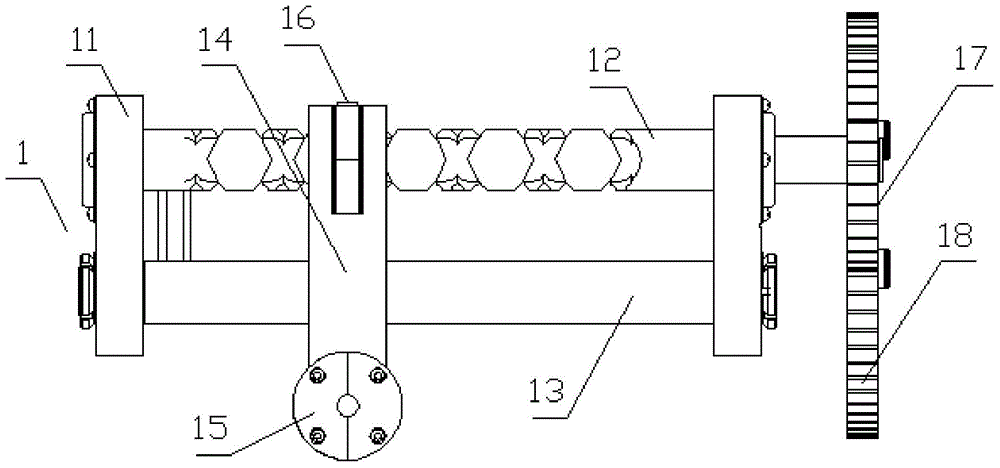
[0018] Such as Figure 1 to Figure 3 As shown, a distribution line pay-off device includes a pay-off rack, a pay-off shaft is rotatably installed on the pay-off rack, a pay-off reel is fixed on the pay-off shaft, and a pay-off shaft is fixedly connected to a Rotate the handle.

[0019] Such as figure 1 As shown, the pay-off frame is provided with a cable arrangement 1, the cable arrangement includes a cable support 11 installed on the pay-off stand, and the cable support is provided with a guide shaft parallel to the outer circumference of the pay-off reel 13 and a reciprocating screw 12, the guide shaft and the reciprocating screw are parallel to the pay-off shaft, the two ends of the reciprocating screw are mounted on the cable support through bearings, the guide shaft is fixed to the cable support, and the reciprocating screw A two-way spiral groove is provided on the top, and a cable moving frame 14 is connected between the guide shaft and the reciprocating screw. Both t...


PUM


Abstract

The invention discloses a distribution line pay-off unit which comprises a pay-off frame. A pay-off shaft is rotationally arranged on the pay-off frame; a pay-off reel is fixedly arranged on the pay-off shaft; the pay-off shaft is fixedly connected with a rotating handle; a brake device for enabling the pay-off reel inertially rotating to brake is arranged on the pay-off frame; meanwhile, a wire arrangement device is arranged on the pay-off frame. According to the invention, on one hand, the distribution line pay-off unit is provided with the brake device, and thus, the distribution line pay-off unit rotates by pulling out a brake control button so as to drive a brake rod to axially move, brake contact surfaces between the brake rod and the pay-off reel are in contact so as to implement brake of the pay-off reel and the distribution line pay-off unit has a simple structure and is convenient to brake; on the other hand, the distribution line pay-off unit is also provided with the wire arrangement device, so that a wire wound on the pay-off reel can be orderly arranged and the distribution line pay-off unit has the simple structure and is convenient to arrange the wire.

Description

technical field [0001] The invention relates to a distribution line pay-off device. Background technique [0002] When laying out wires in the construction of low-voltage distribution lines in rural areas, because the pay-off reel does not have a corresponding brake device, it often results in that after the pay-off is in place, the pay-off reel continues to rotate due to inertia, and the remaining wires on the reel continue to be pushed forward or Make the original tight wires on the wire reel fluffy and disorderly, and it takes a lot of energy to arrange the wires when the wires are set out next time, which causes great inconvenience to the next time the wire setting work. [0003] Therefore, in the current line construction, construction workers generally use tools such as iron rods to generate a certain friction force against the stand in front of the pay-off reel to make the pay-off reel slowly stop. On the other hand, it will also cause wear and tear on the pay-off re...

Claims


Application Information

Patent Timeline
IPC IPC(8): B65H49/18
CPCB65H49/18
Inventor 崔寅潘锋郑涛吴韬杨玉锐吴迪徐福生周武钢王艳潘建乔栾伊斌
Owner STATE GRID CORP OF CHINA
Why Eureka
Try Eureka