Computer embroider machine needle bar cam mechanism with balancing device

A technology of cam mechanism and balance device, which is applied to the mechanism of embroidery machines, embroidery machines, textiles and papermaking, etc. It can solve the problems that affect the service life of embroidery machine heads, the service life of bearings, hinder production efficiency, and cannot increase the speed of rotation, etc., and achieve improvement. Effects of working environment, reducing embroidery thread breakage rate, and eliminating vibration

Inactive Publication Date: 2015-04-01
浙江博盟精工机械有限公司
View PDF8 Cites 7 Cited by
  • Summary
  • Abstract
  • Description
  • Claims
  • Application Information

AI Technical Summary

Problems solved by technology

[0002] In the prior art, the needle bar cam and the thread take-up nylon cam mechanism in the head of the embroidery machine are set as eccentric cams. During the rotation of the eccentric cam, due to the effect of inertia, the head vibrates too much, which not only generates noise but also affects the machine. Head life and embroidery thread breakage rate
Some embroidery machines use eccentric bearings in the needle bar cam mechanism, and use rolling friction instead of sliding friction. Although it can reduce friction and vibration noise, it still cannot improve the vibration caused by the inertia of the eccentric cam, which affects the stability of the embroidery machine head. The service life and the service life of the bearing cannot increase the speed, which hinders the improvement of production efficiency

Method used


Image

  • Computer embroider machine needle bar cam mechanism with balancing device
  • Computer embroider machine needle bar cam mechanism with balancing device
  • Computer embroider machine needle bar cam mechanism with balancing device

Examples


Embodiment 1

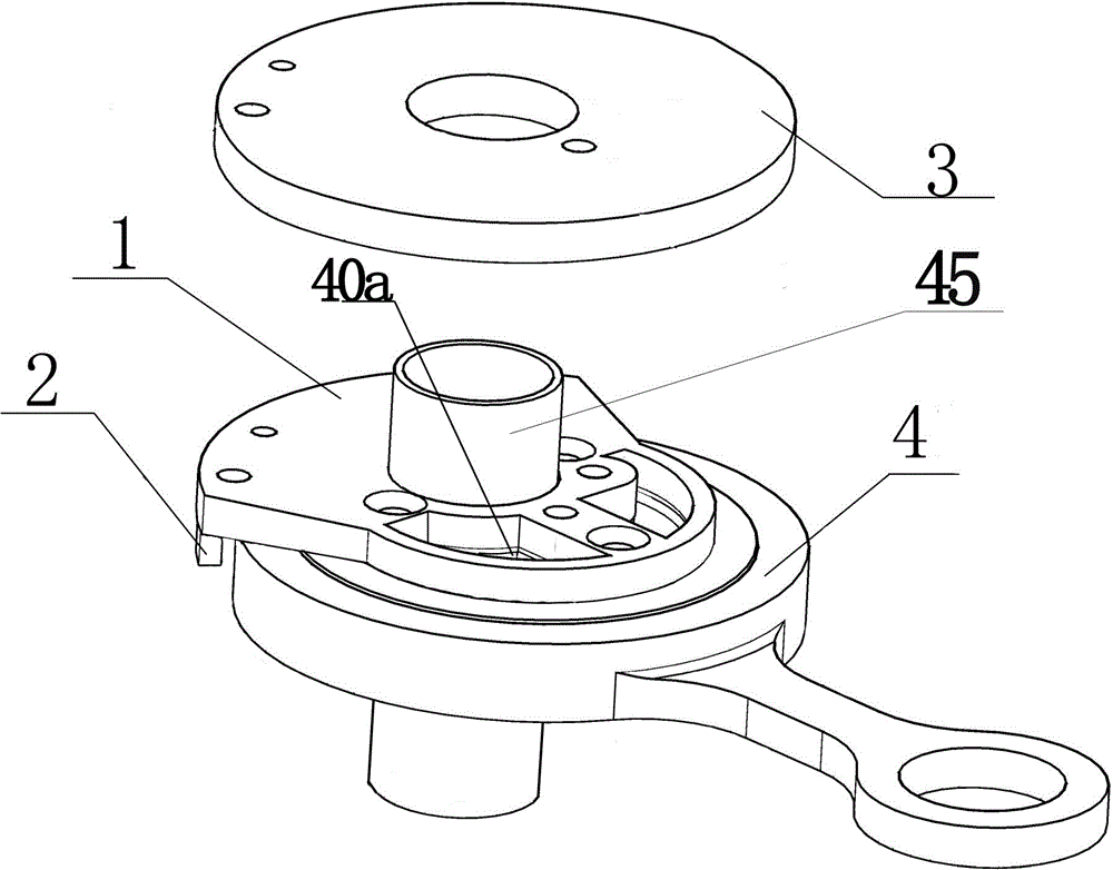
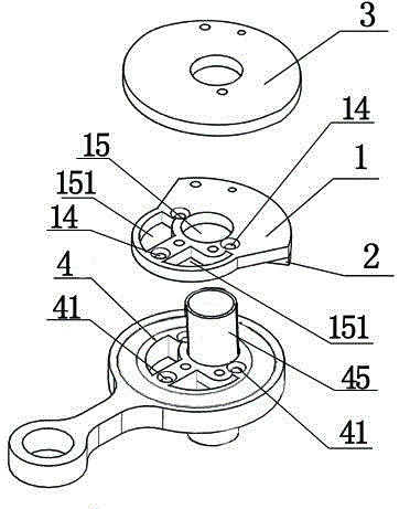
[0027] like Figure 1 to Figure 2 Shown: a computerized embroidery machine needle bar cam mechanism with a balance device, including an eccentric link bearing 4 and a thread take-up nylon cam 3, the eccentric link bearing 4 is the needle bar drive link and needle bar drive cam in the prior art And the bearing between the needle bar driving connecting rod and the needle bar driving cam is an integrally designed and manufactured connecting rod cam integrated bearing. The cam cover 1 is installed on the eccentric connecting rod bearing 4, and the thread take-up is installed on the cam cover 1. Nylon cam3.

[0028] in:

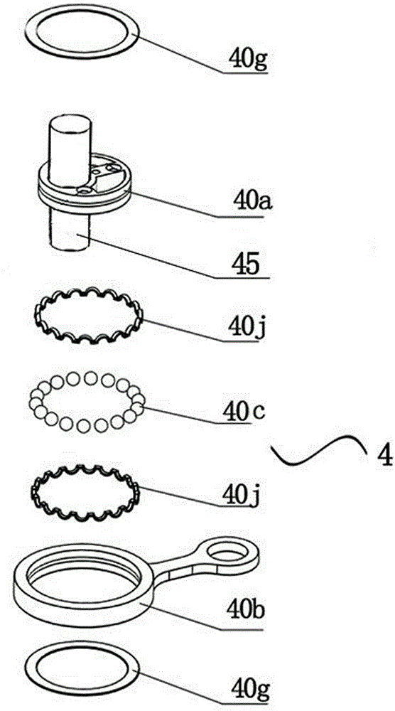
[0029] Eccentric connecting rod bearing 4: such as Figure 1 to Figure 4 As shown, the eccentric connecting rod bearing 4 includes an eccentric bearing inner ring 40a and a connecting rod outer ring 40b; wherein a rotating shaft 45 is arranged on the eccentric bearing inner ring 40a, and several connecting rod outer rings 40b and eccentric bearing inner ring 40a...

Embodiment 2

[0035] In this embodiment, only the cross-sectional shape of the counterweight block 12 in the cam cover plate 1 and the size of the counterweight block 2 are different, and the others are the same as the first embodiment.

[0036] like Figure 6 As shown, in the second embodiment, the cross section of the counterweight block 12 is a sector 17, and the sector 17 includes an inner arc ad171 and an outer arc bc172, wherein the inner arc ad171 is an arc on the circle 18, and the inner arc ad171 is The corresponding central angle is equal to or equal to 90 degrees; the radius of the circle 18 is equal to 22; the center of the outer arc bc172 is the second center 150, the diameter of the outer arc bc172 is 36 mm, and the corresponding central angle of the outer arc bc172 is 180 degrees .

[0037] Counterweight 2: such as figure 1 , figure 2 , image 3 As shown, the corresponding counterweight 2 is arranged on the arc outer edge of the counterweight block 12; the counterweight...

Embodiment 3

[0039] In this embodiment, only the cross-sectional shape of the counterweight block 12 in the cam cover plate 1 and the size of the counterweight block 2 are different, and the others are the same as the first embodiment.

[0040] like Figure 7 As shown, in the third embodiment, the cross section of the counterweight block 12 is a sector 17, and the sector 17 includes an inner arc ad171 and an outer arc bc172, wherein the inner arc ad171 is an arc on the circle 18, and the inner arc ad171 is formed by The corresponding central angle is equal to 133 degrees; the radius of the circle 18 is equal to 23; the center of the outer arc bc172 is the second center 150, the diameter of the outer arc bc172 is 42 mm, and the corresponding central angle of the outer arc bc172 is 180 degrees .

[0041] Counterweight 2: such as figure 1 , figure 2 , image 3 As shown, the counterweight 2 is located on the outer edge of the arc of the counterweight block 12; the counterweight 2 is arra...


PUM


Abstract

The invention discloses a computer embroider machine needle bar cam mechanism with a balancing device. The computer embroider machine needle bar cam mechanism with the balancing device comprises a needle bar transmission cam and a needle bar driving connecting rod, wherein the needle bar driving connecting rod, the needle bar transmission cam and a bearing between the needle bar driving connecting rod and the needle bar transmission cam are integrally designed and manufactured, the integrally manufactured component is an eccentric connecting rod bearing, the eccentric connecting rod bearing comprises an eccentric bearing inner ring, a cam cover plate is arranged on the eccentric bearing inner ring, a line-picking nylon cam is arranged on the cam cover plate, a balancing weight is arranged on the cam cover plate, and the cam cover plate and the balancing weight are used for balancing centrifugal force generated when the line-picking nylon cam and the eccentric connecting rod bearing run. The computer embroider machine needle bar cam mechanism with the balancing device has the beneficial effects that the assembly precision and the mechanical strength of the needle bar driving connecting rod are improved, the service life of an embroider machine head and the eccentric bearing between the needle bar cam and the line-picking nylon cam are prolonged, the reliability of the machine is improved, and the durability and the economical efficiency are improved.

Description

technical field [0001] The invention relates to a computerized embroidery machine, in particular to a needle bar cam mechanism of a computerized embroidery machine with a balance device. Background technique [0002] In the prior art, the needle bar cam and the thread take-up nylon cam mechanism in the head of the embroidery machine are set as eccentric cams. During the rotation of the eccentric cam, due to the effect of inertia, the head vibrates too much, which not only generates noise but also affects the machine. Head life and embroidery thread breakage rate. Some embroidery machines use eccentric bearings in the needle bar cam mechanism, and use rolling friction instead of sliding friction. Although it can reduce friction and vibration noise, it still cannot improve the vibration caused by the inertia of the eccentric cam, which affects the stability of the embroidery machine head. The service life and the service life of the bearing cannot be increased, which hinders ...

Claims


Application Information

Patent Timeline
Patent Type & Authority Applications(China)
IPC IPC(8): D05C11/06
CPCD05C11/06
Inventor 毛子铃王训武
Owner 浙江博盟精工机械有限公司
Why Eureka
Try Eureka