Reversed assembling method of upright cylindrical equipment

A vertical and cylindrical technology, applied in the field of flip-chip, can solve the problems of hydraulic jacking device that cannot be adjusted, the quality is not easy to control, and the amount of materials used is large, so as to avoid the use of a large number of measures, and the quality of welding is easy. , to ensure the effect of welding quality

Active Publication Date: 2015-04-01
TIANJIN 20 CONSTR
View PDF7 Cites 7 Cited by
  • Summary
  • Abstract
  • Description
  • Claims
  • Application Information

AI Technical Summary

Problems solved by technology

Both of the above two formal installation methods have the disadvantages of large space required, great safety hazards for high-altitude segmented counterparts, difficult quality control, large amount of materials required for counterpart platforms and segmented groups (accounting for about 1 / 8 of the total weight of the chimney), mechanical High cost and long construction period
The current hydraulic upside-down method for steel chimneys is installed with a hydraulic jacking device. The problems and shortcomings of the hydraulic jacking device used are: 1) one jacking stroke can only lift a section of the cylinder; When it is necessary to change the diameter of the chimney, it is necessary to cut off the section steel by gas cutting. Considering the influence of heat treatment on the material, after three or four times of cutting, it is necessary to replace the new material, resulting in waste of material
More importantly: the support between the columns is welded with section steel, so that the hydraulic jacking device cannot be adjusted, and the adaptability is poor

Method used


Image

  • Reversed assembling method of upright cylindrical equipment
  • Reversed assembling method of upright cylindrical equipment
  • Reversed assembling method of upright cylindrical equipment

Examples


Embodiment Construction

[0043] In order to further understand the invention content, characteristics and effects of the present invention, the following examples are given, and detailed descriptions are as follows in conjunction with the accompanying drawings:

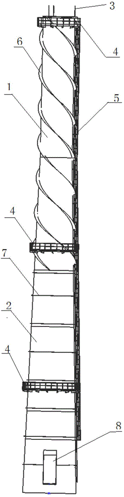
[0044] The invention relates to an upside-down method for vertical cylindrical equipment. The vertical cylindrical equipment is composed of a column section and a cone section, and is installed by a hydraulic lifting device.

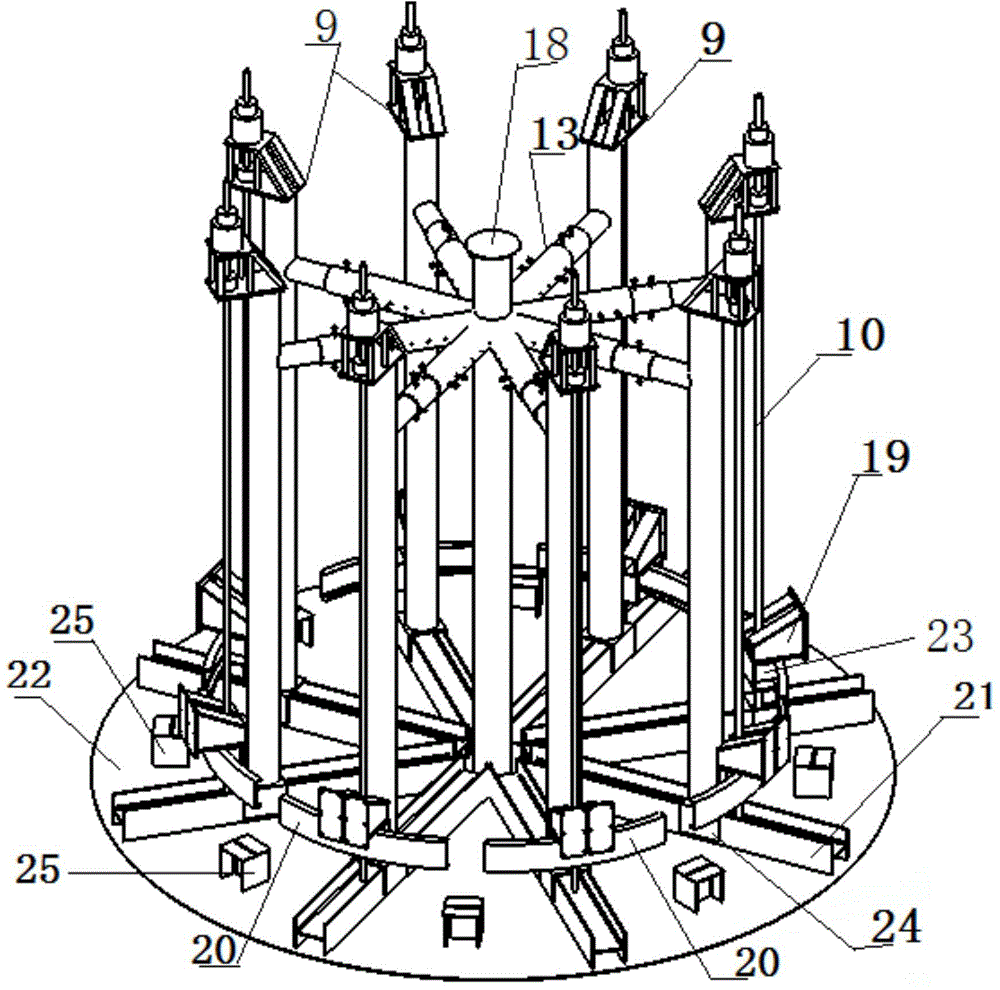
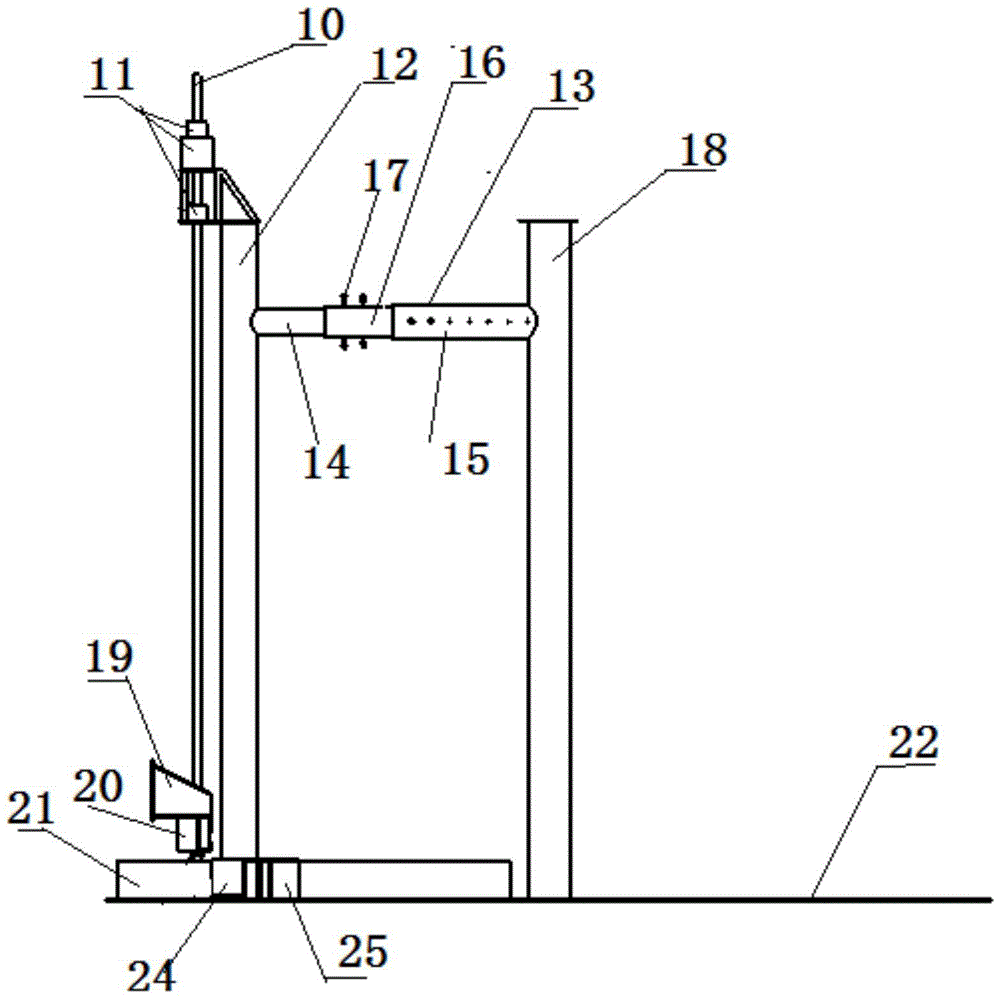
[0045] see Figure 2 to Figure 5 , the hydraulic lifting device includes a horizontally arranged bottom plate 22, a central column 18, a plurality of tubular wall plate buttresses 25 and a plurality of lifting mechanisms 9.

[0046] The central column 18 is fixed vertically at the center of the bottom plate 22 , and all the lifting mechanisms 9 are evenly distributed around the central column 18 along the circumferential direction.

[0047] The lifting mechanism 9 includes a slideway 21, a support column 12, a lifting ...


PUM


Abstract

The invention discloses a reversed assembling method of upright cylindrical equipment; the upright cylindrical equipment consists of a pillar section and a tapered section; the reversed assembling method employs a hydraulic hoisting device for assembling; the hydraulic hoisting device comprises a horizontally arranged base plate, a central pillar, a plurality of cylindrical section wall plate buttresses and a plurality of hoisting mechanisms; in the process of assembling the tapered section of the equipment, the distance from the hoisting mechanisms to the central pillar needs to be adjusted based on the diameter changes of the tapered section of the upright cylindrical equipment. All assembling works of the equipment are implemented in a range of 2 meters above the ground without building up an overhead butt joint welding platform; therefore the danger of dismantling the temporary overhead platform and the potential safety hazard of work staff climbing up and down the overhead platform do not exist, thus greatly increasing the safety; the construction quality is easy to be ensured; land occupied by construction can be reduced; heavy hoisting equipment is not necessary; the construction cost is reduced; and the construction period is saved; the reversed assembling method has a wide application range.

Description

technical field [0001] The invention relates to an inversion method, in particular to an inversion method for upright cylindrical equipment. Background technique [0002] With the development of hot-rolled plates, welding technology and installation technology, coupled with the characteristics of short installation period and low cost of steel chimneys, the application range of steel chimneys is becoming wider and wider. The height of the vertical steel chimney has reached 80-100 meters from 40 meters. The current installation method usually has the following two kinds of normal installation method and hydraulic inversion method: the first is to group the chimney into several sections on the ground, and use a large crane to install it section by section from bottom to top. The second is to install a tower crane of about 20 tons next to the chimney foundation to hoist the chimney in sections. Both of the above two formal installation methods have the disadvantages of large ...

Claims


Application Information

Patent Timeline
Patent Type & Authority Applications(China)
IPC IPC(8): E04H12/34
CPCE04H12/342
Inventor 王彩东冯维斌杜军科郑军朱利强宋晓君
Owner TIANJIN 20 CONSTR
Why Eureka
Try Eureka