Variable valve timing system

A valve phase, variable technology, applied to non-mechanically actuated valves, engine components, machines/engines, etc., to solve problems such as obvious seating impact, difficult adjustment, and complex structure

Inactive Publication Date: 2015-04-01
ZHEJIANG NORMAL UNIVERSITY
View PDF6 Cites 24 Cited by
  • Summary
  • Abstract
  • Description
  • Claims
  • Application Information

AI Technical Summary

Problems solved by technology

[0004] The variable valve timing system already in use generally has a complex structure and is difficult t

Method used


Image

  • Variable valve timing system
  • Variable valve timing system
  • Variable valve timing system

Examples


Embodiment Construction

[0022] The specific embodiments of the present invention will be described in detail below in conjunction with the accompanying drawings, but it should be understood that the protection scope of the present invention is not limited by the specific embodiments. It should be understood that the "top", "bottom", "inner", "outer", "upper", "lower", "left", and "right" mentioned in the following embodiments of the present invention refer to each figure The direction shown is the reference, and the words used to limit the direction are only for the convenience of explanation, and the engine parts have also been simplified and reduced to a certain extent. The positional relationship between the parts shown in the illustration is also for the convenience of explanation Represents the restriction on the specific technical solution of the present invention.

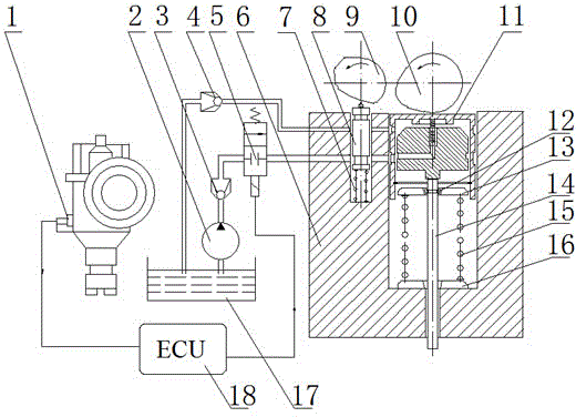
[0023] In the variable valve timing system of the present invention, a variable-lift hydraulic tappet 11 is placed between the in...


PUM


Abstract

The invention discloses a variable valve timing system and relates to engines. According to the variable valve timing system, a variable lift hydraulic tappet component is arranged between an air inlet cam and an air inlet valve, an electronic device is used for judging the working conditions of an engine, when the engine speed is low, the pressure oil supply of an oil pump is cut off, the variable lift hydraulic tappet component only serves as a passive power transmission piece, the air inlet valve is only driven by the air inlet cam, and the air inlet valve has basic air valve opening/closing time, duration time and lift; when the engine speed is high, the pressure oil supply of the oil pump is opened, the variable lift hydraulic tappet component periodically charges and discharges oil under the indirect control of an air inlet valve oil distribution cam, the lift is changed, the air inlet valve is opened before the air inlet cam drive and closed after the drive, and the air inlet valve has air valve opening/closing time, duration time and lift under the high-speed working condition. The variable valve timing system is featured with compact structure, small valve seating impact and easiness in implementation.

Description

technical field [0001] The invention relates to the field of engines, in particular to a variable valve timing. Background technique [0002] Valve timing refers to the opening and closing time and duration of intake and exhaust valves during engine operation. The valve timing of a traditional engine is determined by a valve train with a fixed structure. Regardless of the engine speed, it has a fixed opening and closing time and duration of the intake and exhaust valves relative to the crankshaft, and the valve lift is also determined and unchanged. It can be known from the engine principle that the fixed valve timing is suitable for the engine to run at a certain speed. Below or above this speed, the intake effect of the engine will deteriorate. In fact, the fixed valve timing is a compromise result of taking into account the high and low speed intake effects of the engine. [0003] In order to make the engine have a better air intake effect at high and low speeds, and to...

Claims


Application Information

Patent Timeline
IPC IPC(8): F01L9/02F01L9/04F01L1/34F01L9/10F01L9/20
CPCF01L1/34F01L9/10F01L9/20
Inventor 赵迎生
Owner ZHEJIANG NORMAL UNIVERSITY
Why Eureka
Try Eureka