Pressurizing system mounted on LNG (Liquefied Natural Gas) liquid supplying pipeline and control method of pressurizing system

A technology of liquid supply pipeline and pressurization system, which is applied in the direction of charging system, pump control, oil supply device, etc., and can solve the problems of not meeting the air supply pressure of the engine, energy loss, low cylinder pressure, etc.

Active Publication Date: 2015-04-01
任焕轩
View PDF5 Cites 10 Cited by
  • Summary
  • Abstract
  • Description
  • Claims
  • Application Information

AI Technical Summary

Problems solved by technology

[0003] LNG is the acronym for Liquefied Natural Gas in English. Gas cylinders are gas storage equipment for LNG vehicles. Only when the cylinders supply stable fuel to the engine can the vehicle run stably; When LNG is supplied to the engine, the liquid level in the cylinder gradually decreases, and the gas phase space increases, so that the pressure in the cylinder gradually decreases, so that it cannot meet the gas supply pressure of the engine, and the temperature of the filling fluid is too low. Pressurize the cylinder to ensure a stable output of fuel, that is, the cylinder self-pressurization system
At present, the supercharging method adopted in the market is to use the return air supercharging system to realize supercharging. This kind of supercharging system has problems such as difficult debugging, unstable system, high failure rate, and serious energy loss.

Method used


Image

  • Pressurizing system mounted on LNG (Liquefied Natural Gas) liquid supplying pipeline and control method of pressurizing system
  • Pressurizing system mounted on LNG (Liquefied Natural Gas) liquid supplying pipeline and control method of pressurizing system
  • Pressurizing system mounted on LNG (Liquefied Natural Gas) liquid supplying pipeline and control method of pressurizing system

Examples


Embodiment 1

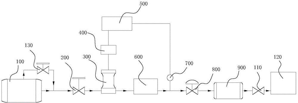
[0029] Embodiment 1: as figure 1 As shown, the pressurization system installed on the LNG liquid supply pipeline, the LNG liquid supply pipeline includes a throttle valve 200, a vaporizer 600, a pressure stabilizing valve 800, a buffer tank 900 and a shut-off valve 110; the LNG storage tank 100 and The engines 120 communicate with each other through the throttle valve 200 , the carburetor 600 , the pressure stabilizing valve 800 , the buffer tank 900 and the shut-off valve 110 in sequence, that is, the LNG storage tank 100 communicates with the carburetor 600 through the throttle valve 200 , the carburetor 600 communicates with the buffer tank 900 through the pressure stabilizing valve 800, the shut-off valve 110 is arranged between the buffer tank 900 and the engine 120; the pressurization system includes a pipeline booster pump 300, pipeline booster pump driving device 400, pressure control unit 500 and pressure sensor 700; the pressure sensor 700 is arranged on the pipeline...


PUM


Abstract

The invention discloses a pressurizing system mounted on an LNG (Liquefied Natural Gas) liquid supplying pipeline and a control method of the pressurizing system. A pressure sensor of the pressurizing system is arranged on a pipeline between a vaporizer and a pressure maintaining valve; the pressure sensor is further connected with the input end of a pressure control unit; the output end of the pressure control unit is connected with the input end of a pipeline pressurizing pump driving device; the output end of the pipeline pressurizing pump driving device is connected with a pipeline pressurizing pump; a liquid inlet end of the pipeline pressurizing pump is communicated with a liquid outlet end of a throttling valve; the liquid outlet end of the pipeline pressurizing pump is connected with the liquid inlet end of the vaporizer. The control method comprises the following steps: A. presetting a standard value of pipeline pressure; B. detecting the pipeline pressure; and C. comparing a detection value with the standard value, wherein when the detection value is less than or equal to the detection value, the pipeline pressurizing pump works; when the detection value is more than the standard value, the pipeline pressurizing pump is at a normally opened state. By the aid of the pressurizing system, the pressure of an LNG bottle set keeps a low-temperature and low-pressure state and an engine obtains stable gas supplying pressure.

Description

technical field [0001] The invention relates to a pressurization system, in particular to a pressurization system installed on an LNG liquid supply pipeline and a control method thereof. Background technique [0002] It is well known that the current application and research of engines all adopt the high-pressure injection air intake method instead of the traditional normal pressure air intake method, so the fuel supply system of LNG vehicles must be able to provide stable high-pressure gas for the engine. The initial liquefied natural gas filled into the storage tank is generally under normal pressure. First, the storage tank must be self-pressurized. When the pressure increases to the rated working pressure range of the natural gas engine, the engine will be supplied with gas. [0003] LNG is the acronym for Liquefied Natural Gas in English. Gas cylinders are gas storage equipment for LNG vehicles. Only when the cylinders supply stable fuel to the engine can the vehicle ru...

Claims


Application Information

Patent Timeline
Patent Type & Authority Applications(China)
IPC IPC(8): F02M21/02F04B45/033F04B39/10F04B49/02
CPCY02T10/30
Inventor 任焕轩
Owner 任焕轩
Why Eureka
Try Eureka