Receiver part complex surface numerical control machining method

A technology for complex shapes and box-like parts, applied in the direction of digital control, electrical program control, etc., can solve problems such as different tangent points, low production efficiency, and lack of CNC machining technology

Inactive Publication Date: 2015-04-01
SHENYANG LIMING AERO-ENGINE GROUP CORPORATION
View PDF6 Cites 5 Cited by
  • Summary
  • Abstract
  • Description
  • Claims
  • Application Information

AI Technical Summary

Problems solved by technology

[0002] With the maturity of engine manufacturing technology, the overall structure of casing parts is also becoming more complex and the processing methods are becoming more diversified; more and more parts adopt more complex design structures, and the wool of parts is also Precision castings that are more difficult to manufacture are used, which puts forward higher requirements for the processing technology of parts; due to the current imperfection of precision casting technology, coupled with the complexity of the structure of parts, the limitation of hardware structure of processing equipment and the limitation of numerical control processing technology Due to the shortage and other reasons, the processing of complex profiles of casing parts has been at a low level, which affects the dimensional accuracy, surface quality and overall processing cycle of the parts.
[0003] In the

Method used


Image

  • Receiver part complex surface numerical control machining method
  • Receiver part complex surface numerical control machining method
  • Receiver part complex surface numerical control machining method

Examples


Embodiment Construction

[0021] An embodiment of the present invention will be further described below in conjunction with the accompanying drawings.

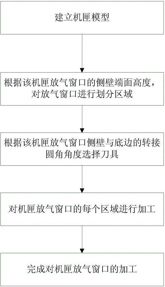
[0022] A numerical control machining method for the vent window of casing parts, the flow chart of the method is as follows figure 1 shown, including the following steps:

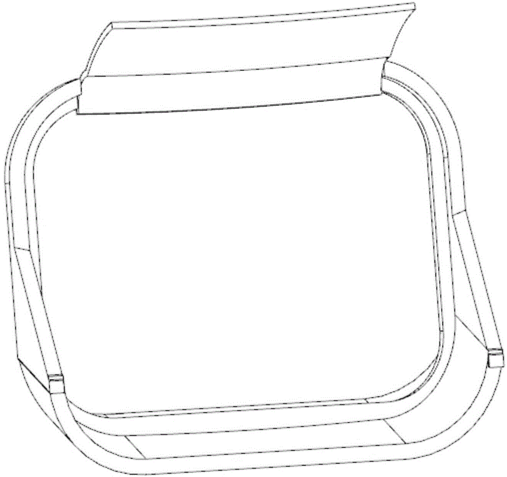
[0023] Step 1, establish the casing model;

[0024] In the embodiment of the present invention, the basis for processing the deflation window is to create an accurate processing model, and only by relying on an accurate part model can a correct and reasonable tool path be created; therefore, in the embodiment of the present invention, UG is used to build Modeling and programming software creates a set of part models, such as figure 2 As shown, it laid the foundation for the subsequent programming work;

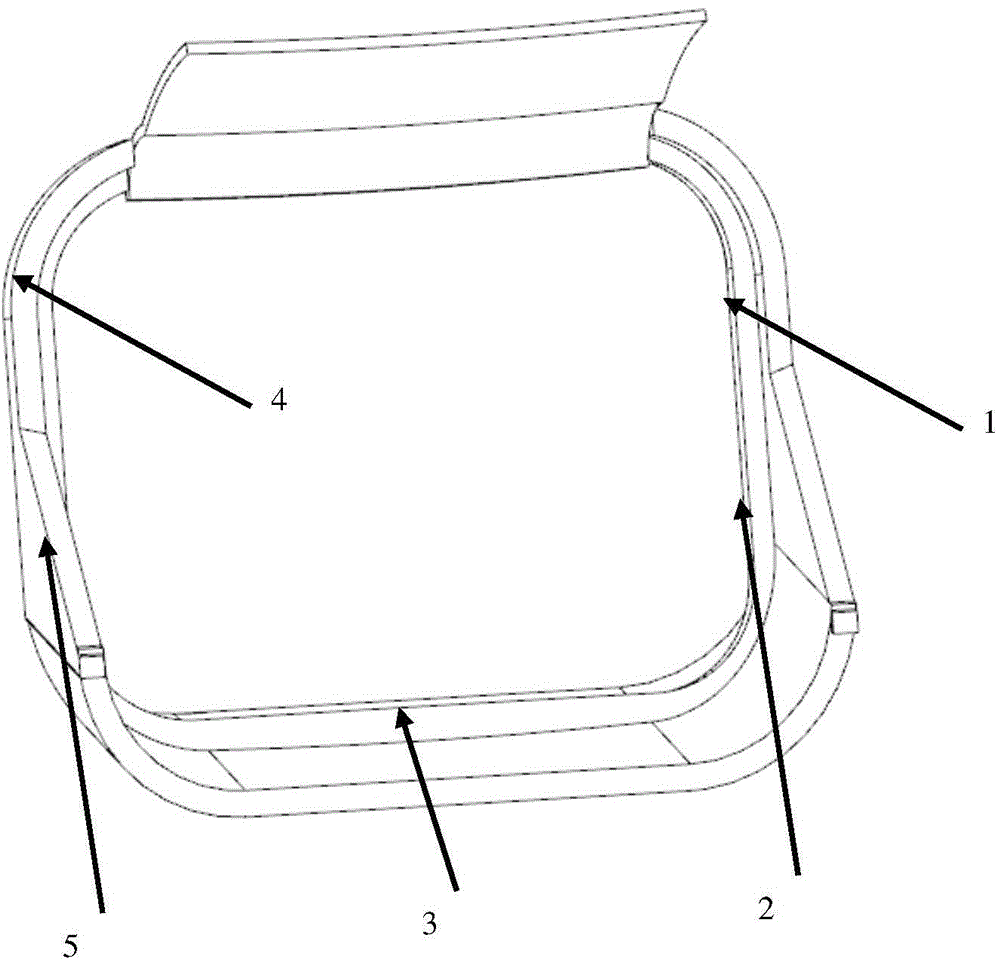
[0025] Step 2, according to the height of the side wall end surface of the air release window of the casing, the air release window is divided into regions;

[0026] When milli...


PUM


Abstract

The invention provides a receiver part complex surface numerical control machining method and belongs to the machine manufacturing field. The method adopts a segmental machining method, solves the difficulty of complex surface numerical control machining, and meanwhile, provides a thinking direction for resolving similar problems. According to the method, through analyzing part structure features, a machining surface is manually divided into a plurality of areas, and influences of different surfaces on cutters during programming are fully known; operation is established for different machining areas, thereby simplifying the programming process; and solution schemes are made for the influences, so that cutting points of the cutters are optimized, machining quality of the parts is improved, machining effect is improved, and the problem that the machining field is blank is fundamentally solved.

Description

technical field [0001] The invention belongs to the field of mechanical manufacturing, and in particular relates to a numerical control machining method for complex profiles of casing parts. Background technique [0002] With the maturity of engine manufacturing technology, the overall structure of casing parts is also becoming more complex and the processing methods are becoming more diversified; more and more parts adopt more complex design structures, and the wool of parts is also Precision castings that are more difficult to manufacture are used, which puts forward higher requirements for the processing technology of parts; due to the current imperfection of precision casting technology, coupled with the complexity of the structure of parts, the limitation of hardware structure of processing equipment and the limitation of numerical control processing technology Due to the shortage and other reasons, the machining of complex profiles of casing parts has always been at a ...

Claims


Application Information

Patent Timeline
IPC IPC(8): G05B19/18
CPCG05B19/19
Inventor 王传滨郝卓张建国
Owner SHENYANG LIMING AERO-ENGINE GROUP CORPORATION
Why Eureka
Try Eureka